Diagnosis Procedure
Description
Calibration must be performed after replacing or removing/installing the following parts..
- Head Up Display unit
- Windshield glass
- Steering member
Diagnosis Procedure
| note |
|
1.TARGET PREPARATION
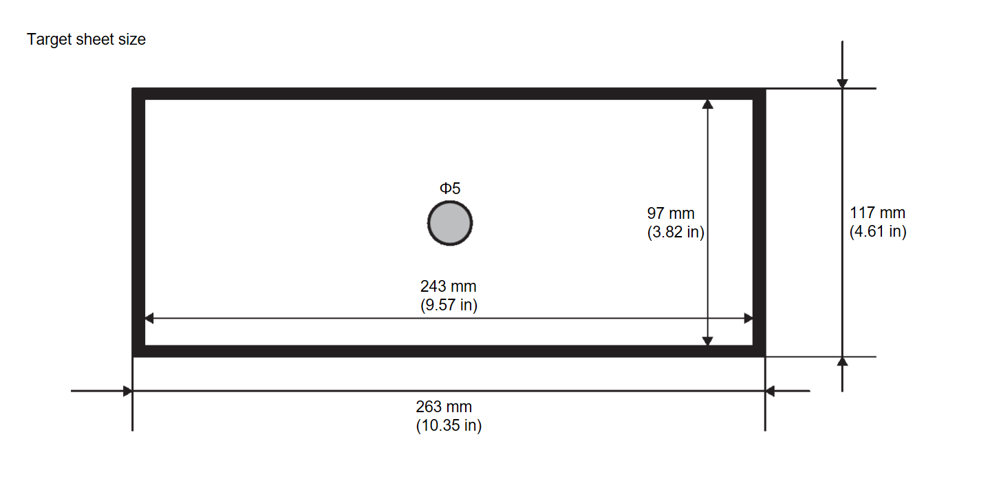
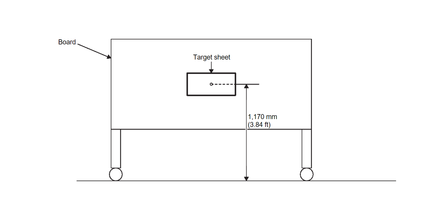
Prepare the distortion calibration jig according to the following procedure and the figure.
- Prepare target sheet according to the figure.
- Paste the created target sheet onto the board according to the figure.
2.TARGET SETTING
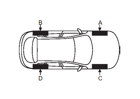
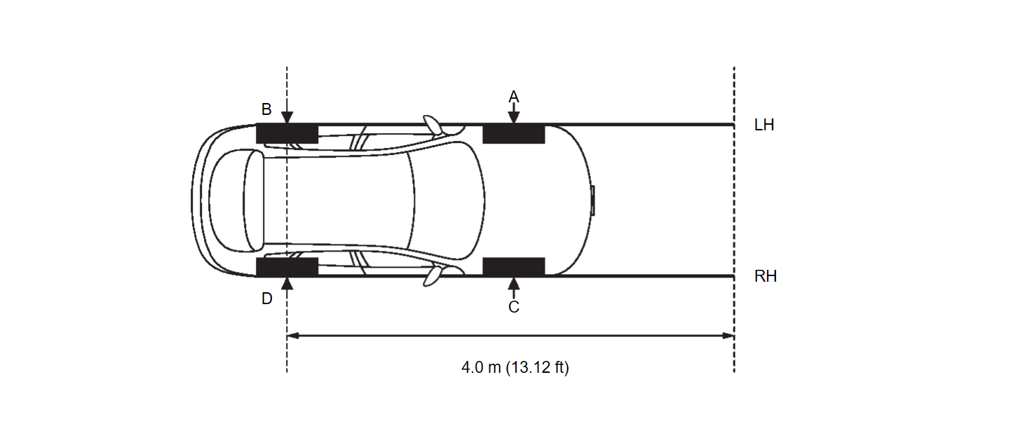
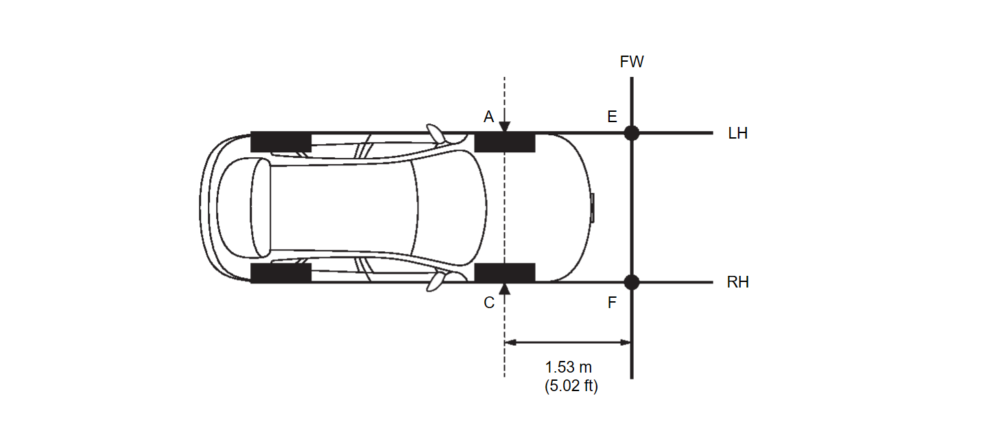
- Mark points “A”, “B”, “C” and “D” at the center position of each wheels.
- Draw line "LH (RH)" passing through points "A (C)" and "B (D)" on the left (right) side of vehicle.
note Approximately 4.0 m (13.12 ft) or more from the point "B (D)". - Mark point "E (F)" on the line "LH (RH)" at the positions 1.53 m (5.02 in) from point "A (C)". And then draw line "FW" passing through the points "E" and "F".
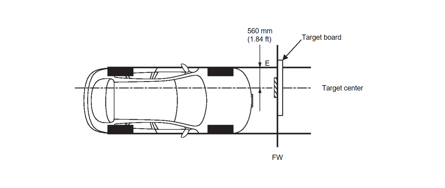
- Place the target board on the line "FW" so that the center of the target comes to 560 mm (1.84 ft) from mark point "E".
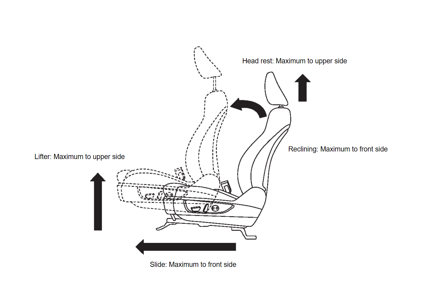
3.DRIVER'S SEAT POSITION ADJUSTMENT
4.RESET OPERATION
- Turn the electric motor switch ON.
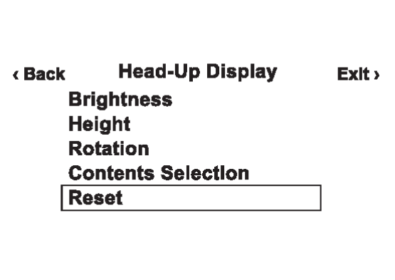
- Touch "Reset" on the Head Up Display setting screen of the combination meter and reset the setting. Refer to Switch Name and Function
 .
.
5.TARGET CENTER POSITION ADJUSTMENT
 With M.U.T.-III SE
- Select "Distortion calibration" of "Special Function" on "E-HUD" using M.U.T.-III SE.
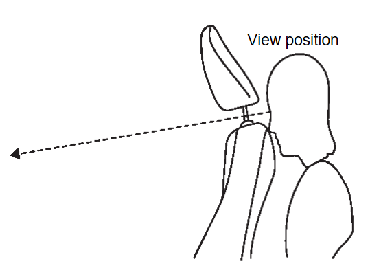
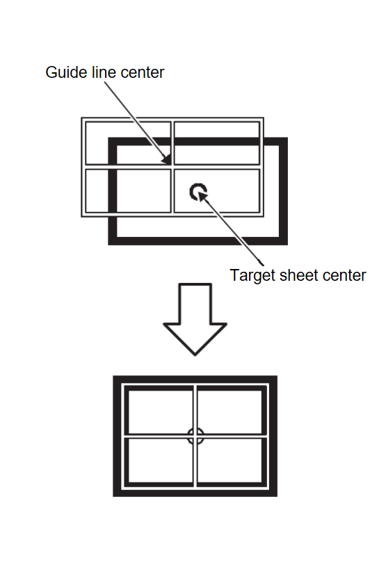
- Confirm from the between seatback and headrest whether the center position of the displayed guideline is coincident with the center position of the target sheet.
| note | If there is a gap between the target sheet and the guideline, move the target board so that the center of the target seat coincides with the center of the guideline. |
6.PERFORM DISTORTION CALIBRATION
 With M.U.T.-III SE
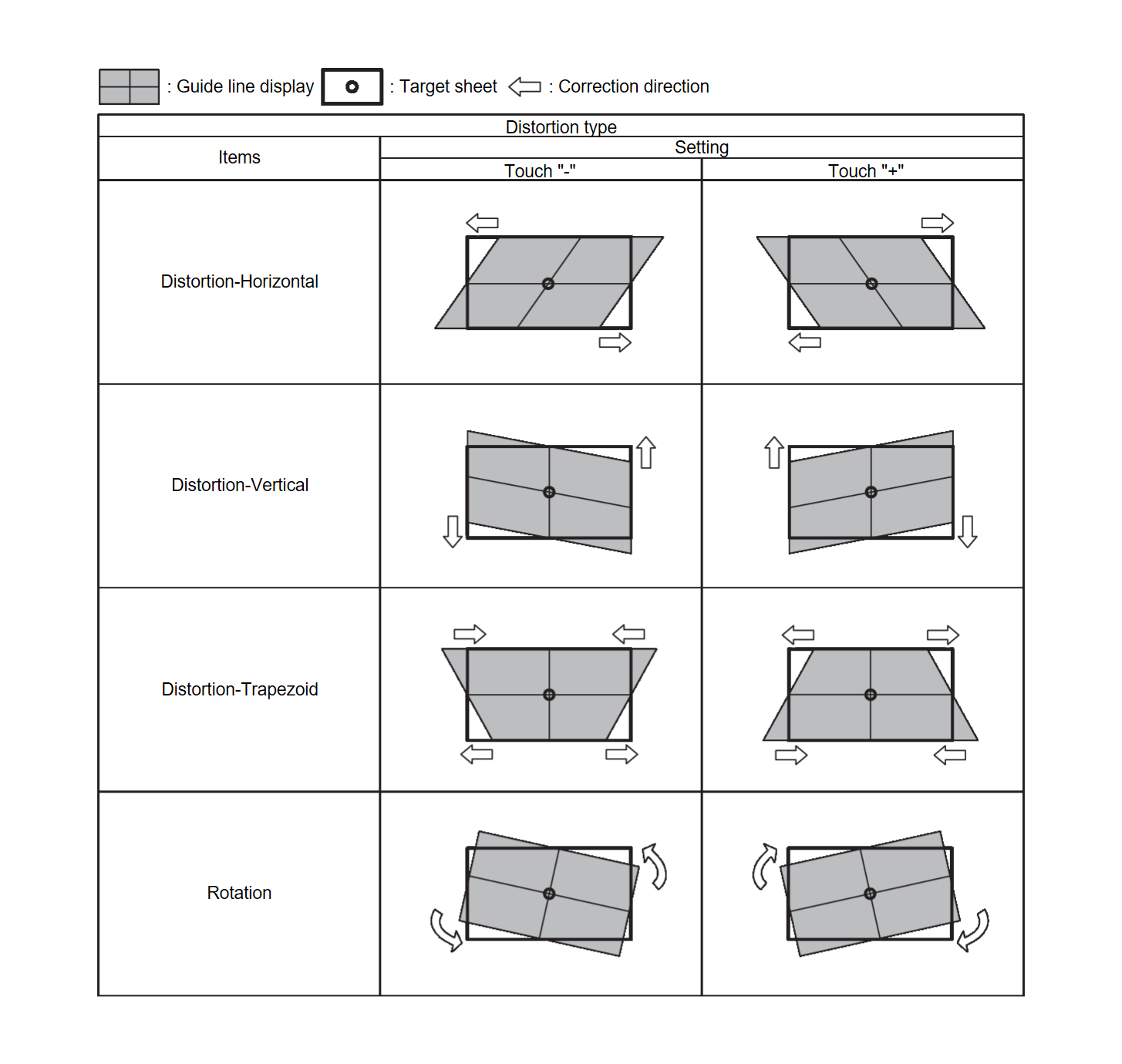
- Check the distortion of the guideline from the between seatback and headrest.
- If the guideline display is distorted, touch "+" or "-" of the item corresponding to the distortion type to be corrected according to following table, and calibrate to match the target sheet.
- Touch "Save" and save the setting when calibration is completed.
note Touch "Reset" to cancel the change.
: WORK END
![[Previous]](../../../buttons/fprev.png)
![[Next]](../../../buttons/fnext.png)
