System Description
DESCRIPTION
- CAN (Controller Area Network) is a serial communication line for real time application. It is an on-vehicle multiplex communication line with high data communication speed and excellent error detection ability. Many electronic control units are equipped onto a vehicle, and each control unit shares information and links with other control units during operation (not independent). In CAN communication, control units are connected with 2 communication lines (CAN-H line, CAN-L line) allowing a high rate of information transmission with less wiring. Each control unit transmits/receives data but selectively reads required data only.
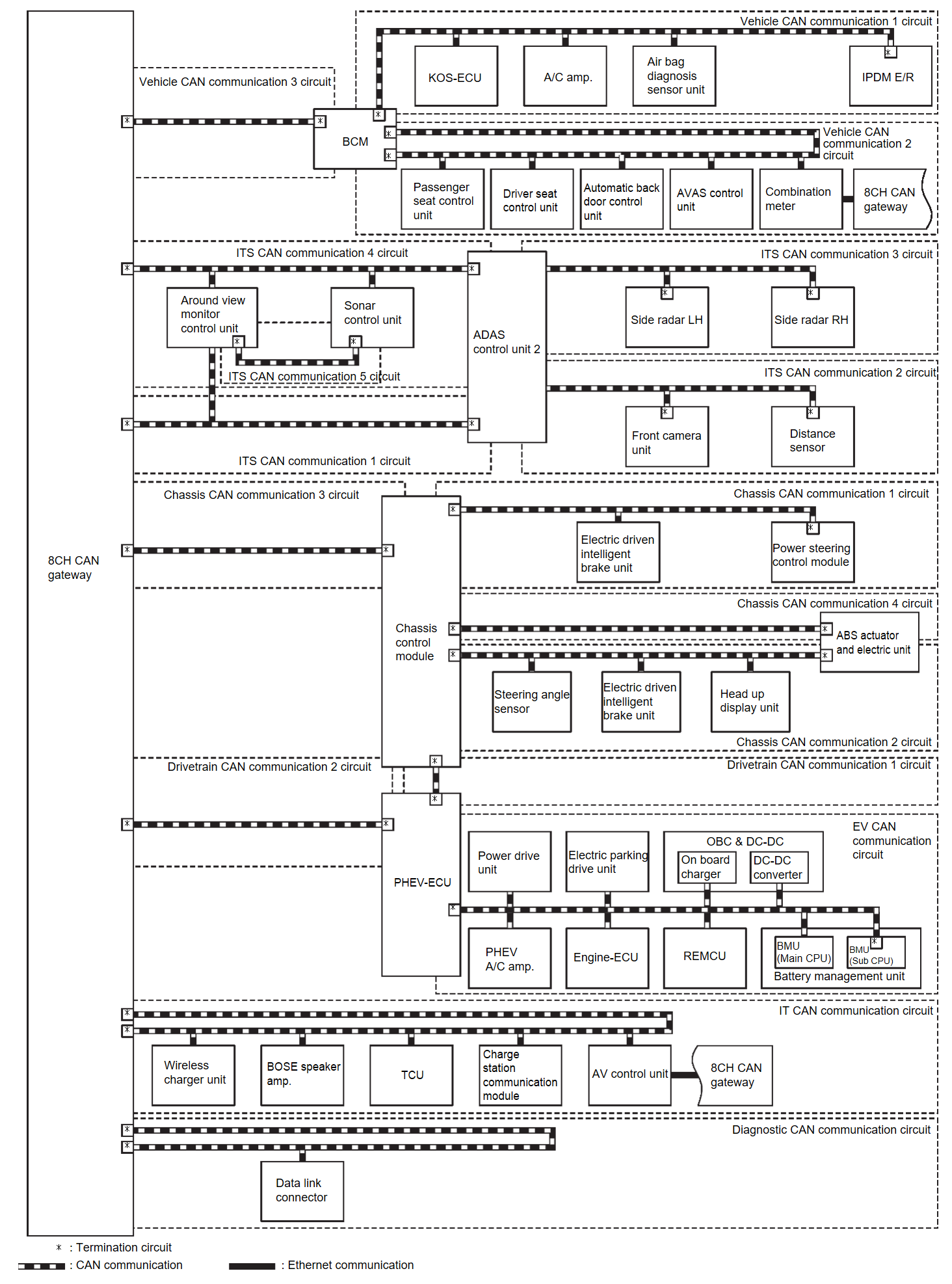
- The following control units include a gateway function and communicate signals between the different CAN communication circuits.
CAN communication circuit Gateway control unit Reference Between the following circuits. - Vehicle CAN communication 1 circuit
- Vehicle CAN communication 2 circuit
- Vehicle CAN communication 3 circuit
BCM System Description 
Between the following circuits. - Vehicle CAN communication 3 circuit
- ITS CAN communication 1 circuit
- ITS CAN communication 4 circuit
- Chassis CAN communication 3 circuit
- Drivetrain CAN communication 2 circuit
- IT CAN communication circuit
- Diagnostic CAN communication circuit
8CH CAN gateway 8CH CAN GatewayComponent Description 
Between the following circuits. - ITS CAN communication 1 circuit
- ITS CAN communication 2 circuit
- ITS CAN communication 3 circuit
- ITS CAN communication 4 circuit
ADAS control unit 2 ADAS Control Unit 2 
Between the following circuits. - Chassis CAN communication 1 circuit
- Chassis CAN communication 2 circuit
- Chassis CAN communication 3 circuit
- Chassis CAN communication 4 circuit
- Drivetrain CAN communication 1 circuit
Chassis control module System Description 
Between the following circuits. - ITS CAN communication 1 circuit
- ITS CAN communication 4 circuit
- ITS CAN communication 5 circuit
Around view monitor control unit Around View Monitor Control Unit 
ITS CAN communication 4 circuit ⇔ ITS CAN communication 5 circuit Sonar control unit Sonar Control Unit 
Chassis CAN communication 2 circuit ⇔ Chassis CAN communication 4 circuit ABS actuator and electric unit System Description 
Between the following circuits. - Drivetrain CAN communication 1 circuit
- Drivetrain CAN communication 2 circuit
- Engine CAN communication circuit
PHEV-ECU GENERAL INFORMATION 
CAN Communication Signal Generation
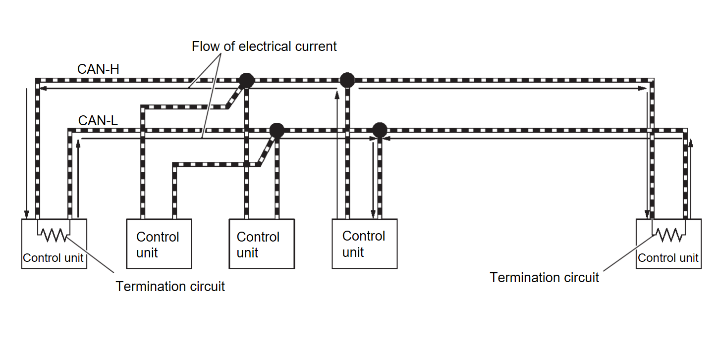
- Termination circuits (resistors) are connected across the CAN communication system. When transmitting a CAN communication signal, each control unit passes a current to the CAN-H line and the current returns to the CAN-L line.
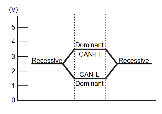
- The current flows separately into the termination circuits connected across the CAN communication system and the termination circuits drop voltage to generate a potential difference between the CAN-H line and the CAN-L line.
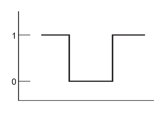
note A signal with no current passage is called “Recessive” and one with current passage is called “Dominant”. - The system produces digital signals for signal communications, by using the potential difference.
The Construction of CAN Communication Signal (Message)
| No. | Message name | Description |
| 1 | Start of frame (1 bit) | Start of message. |
| 2 | Arbitration of field (11 bit) | Priorities of message-sending are shown when there is a possibility that multiple messages are sent at the same time. |
| 3 | Control field (6 bit) | Signal quantity in data field is shown. |
| 4 | Data field (0-64 bit) | Actual signal is shown. |
| 5 | CRC field (16 bit) |
|
| 6 | ACK field (2 bit) | The completion of normal reception is sent to the transmitting unit. |
| 7 | End of frame (7 bit) | End of message. |
CAN Communication Line
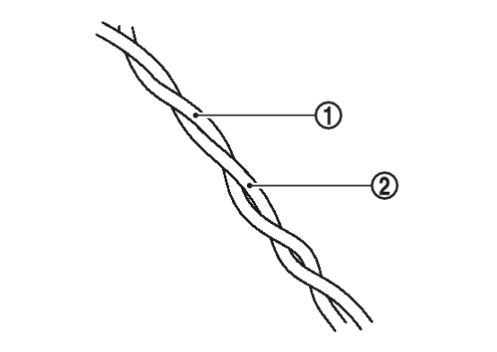
The CAN communication line is a twisted pair wire consisting of strands of CAN-H  and CAN-L
  and has noise immunity.
 and CAN-L
  and has noise immunity.
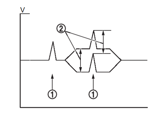
| note | The CAN communication system has the characteristics of noise-resistant because this system produces digital signals by using the potential difference between the CAN-H line and the CAN-L line and has the twisted pair wire structure. Since the CAN-H line and the CAN-L line are always adjacent to each other, the same degree of noise occurs, respectively, when a noise  occurs. Although the noise changes the voltage, the potential difference occurs. Although the noise changes the voltage, the potential difference  between the CAN-H line and the CAN-L line is insensitive to noise. Therefore, noise-resistant signals can be obtained. between the CAN-H line and the CAN-L line is insensitive to noise. Therefore, noise-resistant signals can be obtained. |
CAN Signal Communications
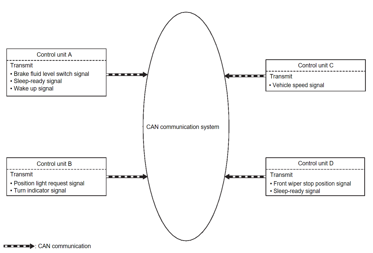
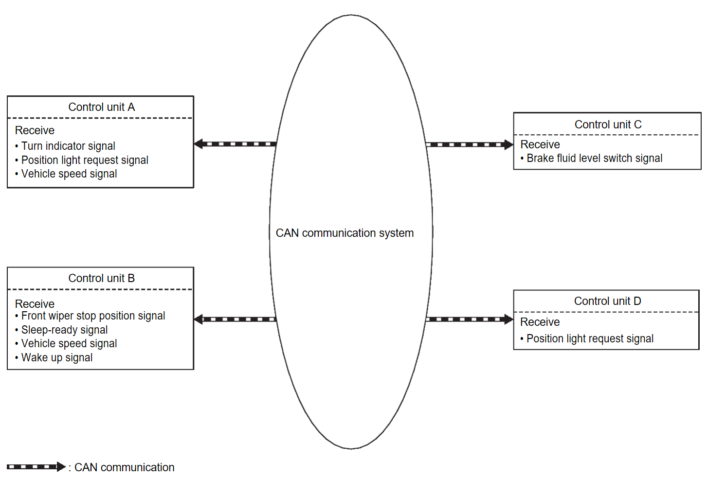
Each control unit of the CAN communication system transmits signals through the CAN communication control circuit included in the control unit and receives only necessary signals from each control unit to perform various kinds of control.
| note | The above signal names and signal communications are provided for reference purposes. For CAN communications signals of this vehicle, refer to CAN Communication Signal Chart . . |
![[Previous]](../../../buttons/fprev.png)
![[Next]](../../../buttons/fnext.png)
