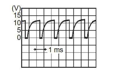
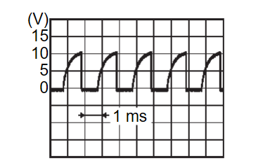
Diagnosis Procedure
1.Front blower motor control signal check
- Change the power supply mode of the electric motor switch to ON (READY indicator: ON).
- Check duty ratios between Front blower motor harness connector and ground by using an oscilloscope.
Is the inspection result normal?
 Replace A/C amp. Refer to Removal and Installation
 .
.2.Check front blower motor control signal circuit for short to power supply
- Change the power supply mode of the electric motor switch to ON (READY indicator: ON).
- Disconnect A/C amp. connector and front blower motor connector.
- Check continuity between A/C amp. harness connector and front blower motor harness connector.
A/C amp. Front blower motor Voltage Connector Terminal Connector Terminal M54 34 M144 1 Not existed
Is the inspection result normal?
 Replace front blower motor Refer to Removal and Installation
 .
. Repair harnesses or connector.
![[Previous]](../../../buttons/fprev.png)
![[Next]](../../../buttons/fnext.png)

