Diagnosis Procedure
1.CHECK INTAKE SENSOR SIGNAL
- Change the power supply mode of the electric motor switch to ON (READY indicator: ON).
- Check voltage between A/C amp. harness connector.
Is the inspection result normal?
 Replace A/C amp. Refer to Removal and Installation
 .
.2.CHECK INTAKE SENSOR POWER SUPPLY
- Turn the electric motor switch OFF.
- Disconnect intake sensor connector.
- Turn the electric motor switch ON.
- Check voltage between intake sensor harness connector and ground.
+ - Voltage (Approx.)Intake sensor Connector Terminal M135 1 Ground 5 V
Is the inspection result normal?
3.CHECK INTAKE SENSOR GROUND CIRCUIT FOR OPEN
- Turn the electric motor switch OFF.
- Disconnect A/C amp. connector.
- Check continuity between intake sensor harness connector and A/C amp. harness connector.
Intake sensor A/C amp. Continuity Connector Terminal Connector Terminal M135 2 M54 26 Existed
Is the inspection result normal?
 Repair harness or connector.
4.CHECK INTAKE SENSOR
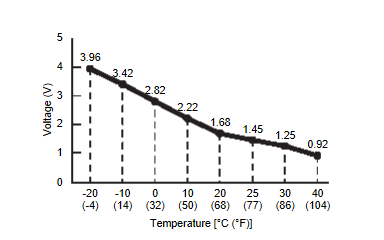
Check intake sensor. Refer to Component Inspection .
. Replace A/C amp. Refer to Removal and Installation
 .
. Replace intake sensor. Refer to Component Inspection
 .
.
 .
.Is the inspection result normal?
 Replace A/C amp. Refer to Removal and Installation
 .
. Replace intake sensor. Refer to Component Inspection
 .
.5.CHECK INTAKE SENSOR POWER SUPPLY CIRCUIT FOR OPEN
- Turn the electric motor switch OFF.
- Disconnect A/C amp. connector.
- Check continuity between intake sensor harness connector and A/C amp. harness connector.
Intake sensor A/C amp. Continuity Connector Terminal Connector Terminal M135 1 M54 23 Existed
Is the inspection result normal?
 Repair harness or connector.
6.CHECK INTAKE SENSOR POWER SUPPLY CIRCUIT FOR SHORT
Check voltage between intake sensor harness connector and ground.
 Replace A/C amp. Refer to Removal and Installation
 .
. Repair harness or connector.
| + | - | Voltage (Approx.) | |
| Intake sensor | |||
| Connector | Terminal | ||
| M135 | 1 | Ground | 0 V |
Is the inspection result normal?
 Replace A/C amp. Refer to Removal and Installation
 .
. Repair harness or connector.
![[Previous]](../../../buttons/fprev.png)
![[Next]](../../../buttons/fnext.png)
