DIAGNOSTIC FUNCTION
HOW TO CONNECT THE M.U.T.-III SE
Required Special Tools:
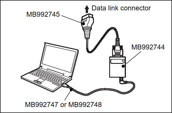
- MB992744: Vehicle communication interface-Lite (V.C.I.-Lite)
- MB992745: V.C.I.-Lite main harness A
- MB992747: V.C.I.-Lite USB cable short
- MB992748: V.C.I.-Lite USB cable long
| caution | To prevent damage to M.U.T.-III SE, always turn OFF the power supply mode of the electric motor switch before connecting or disconnecting M.U.T.-III SE. |
1. Ensure that the power supply mode of the electric motor switch is OFF.
2. Start up the personal computer.
4. Connect special tool MB992745 to special tool MB992744.
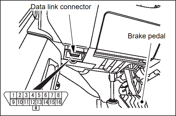
5. Connect special tool MB992745 to the data link connector.
| note | When the special tool MB992745 is connected to the data link connector, the special tool MB992744 indicator light will be illuminated in a green color. |
6. Start the M.U.T.-III SE system on the personal computer.
| note | Disconnecting M.U.T.-III SE is the reverse of the connecting sequence, making sure that the power supply mode of the electric motor switch is OFF. |
HOW TO READ AND ERASE DIAGNOSTIC TROUBLE CODES
Required Special Tools:
- MB992744: Vehicle communication interface-Lite (V.C.I.-Lite)
- MB992745: V.C.I.-Lite main harness A
- MB992747: V.C.I.-Lite USB cable short
- MB992748: V.C.I.-Lite USB cable long
| caution | To prevent damage to M.U.T.-III SE, always turn OFF the power supply mode of the electric motor switch before connecting or disconnecting M.U.T.-III SE. |
2. Turn the power supply mode of the electric motor switch to ON.
3. Select "OBC" or "DC/DC" from system select screen of the M.U.T.-III SE.
4. Select "Diagnostic Trouble Code" to read the DTC.
5. If a DTC is set, it is shown.
6. Choose "Erase DTCs" to erase the DTC.
HOW TO READ DATA LIST
Required Special Tools:
- MB992744: Vehicle communication interface-Lite (V.C.I.-Lite)
- MB992745: V.C.I.-Lite main harness A
- MB992747: V.C.I.-Lite USB cable short
- MB992748: V.C.I.-Lite USB cable long
| caution | To prevent damage to M.U.T.-III SE, always turn off the power supply mode of the electric motor switch before connecting or disconnecting M.U.T.-III SE. |
2. Turn the power supply mode of the electric motor switch to ON.
3. Select "OBC" or "DC/DC" from system select screen of the M.U.T.-III SE.
4. Select "Data List."
5. Choose an appropriate item and select the "OK" button.
HOW TO DIAGNOSE THE CAN BUS LINES
Required Special Tools:
- MB992744: Vehicle communication interface-Lite (V.C.I.-Lite)
- MB992745: V.C.I.-Lite main harness A
- MB992747: V.C.I.-Lite USB cable short
- MB992748: V.C.I.-Lite USB cable long
| caution | To prevent damage to M.U.T.-III SE, always turn off the power supply mode of the electric motor switch before connecting or disconnecting M.U.T.-III SE. |
2. Turn the power supply mode of the electric motor switch to ON.
3. Perform the CAN bus diagnostics (Refer to ELECTRICAL & POWER CONTROL – LAN system, CAN Fundamental, Basic Inspection, Diagnosis and Repair Workflow EXPLANATION ABOUT THE SCAN TOOL (M.U.T.-III SE) CAN BUS DIAGNOSTICS ).
).
 ).
).FREEZE FRAME DATA CHECK
By using M.U.T.-IIISE, the freeze frame data can be checked.
When detecting fault and setting the DTC, the ECU connected to CAN bus line obtains the data when the DTC is determined, and then stores the ECU status of that time. By analysing each data using M.U.T.-IIISE, troubleshooting can be carried out efficiently. The displayed items are as the table below.
DISPLAY ITEM LIST (OBC)
| Item No. | M.U.T.-IIISE display | Unit or value |
| 10 | ODO/TRIP METER | km/mile |
| 20 | DTC No | Value is displayed |
| 30 | CHARGE TYPE | Not active/AC CHARGE 100V/AC CHARGE 200V/DC CHARGE/V2X/DC GB |
| 40 | ACCUMULATION ABNORMALITY STOP NUMBER OF TIMES | Value is displayed |
| 50 | This charge time | min |
| 60 | IGCT VOLTAGE | V |
| 70 | PFC TEMPERATURE | °C/°F |
| 80 | VOLTAGE UP DEPARTMENT TEMPERATURE1 | °C/°F |
| 90 | VOLTAGE UP DEPARTMENT TEMPERATURE2 | °C/°F |
| 100 | INSIDE TEMPERATURE | °C/°F |
| 110 | CHOT STATUS | Lo/Hi |
| 120 | PLUGIN CHG STATUS | No HV charge/HV battery Charge |
| 130 | ABNORMAL STOP INFORMATION | OFF/ON |
| 140 | EEPROM write complete | Complete/In writing |
| 150 | S2SW | OFF/ON |
| 160 | CHOT STATUS(CAN) | Lo/Hi |
| 170 | COOLING REQUEST STATE | OFF/ON |
| 180 | IGCT POWER HOLD STATE | OFF/ON |
| 190 | PFC START SIGNAL | STOP/START |
| 200 | INPUT CURRENT Zero Point Confirmation flag | Disallowed/Permissions |
| 210 | Limit history(INPUT VOLTAGE) | No Limit history/Limit history/N/A/Under Limits |
| 220 | Limit history(Temperature) | No Limit history/Limit history/N/A/Under Limits |
| 230 | CELL MAX TEMPERATURE | °C/°F |
| 240 | CELL MIN TEMPERATURE | °C/°F |
| 250 | BATTERY CURRENT | A |
| 260 | CHARGE IN OPERATION | OFF/ON |
| 270 | VEHICLE ABNORMAL STOP INFORMATION | OFF/ON |
| 280 | CHG START STATUS | No request/Charge start request/Main contactor ON request |
| 290 | OBC CONTROL STATE | SLEEP MODE/OBC WAIT MODE/IDLING MODE/DC CHARGE MODE/AC CHARGE MODE/CHARGE END MODE |
| 300 | OBC CONTROL STATE(AC CHARGE) | OUT OF THE AC CHARGE MODE/AC CHARGE START MODE/AC CHARGE MODE/AC CHARGE STOP MODE/AC CHARGE END MODE |
| 310 | S2 SWICH STATE | OFF/ON |
| 320 | CHG GUN STATUS | Not/Half insert/Insert |
| 330 | DC CHARGE/DISCHARGE SUB MODE | OUT OF THE DC CHARGE MODE/CHADEMO CHARGE/CHADEMO CHARGE AND DISCHARGE |
| 340 | DC CHG GUN STATUS | Not connect/Connect/Connect and switch M OFF |
| 350 | D1 SIGNAL | OFF/ON |
| 360 | D2 SIGNAL | OFF/ON |
| 370 | SWICH K STATE | OFF/ON |
| 380 | SWICH M STATE | OFF/ON |
| 390 | DC CONTACTOR STATE(P) | OFF/ON |
| 400 | DC CONTACTOR STATE(N) | OFF/ON |
| 410 | ACCUMULATION CHARGE NUMBER OF TIMES(100V) | Value is displayed |
| 420 | ACCUMULATION CHARGE NUMBER OF TIMES(200V) | Value is displayed |
| 430 | ACCUMULATION CHARGE TIMES(100V) | Value is displayed |
| 440 | ACCUMULATION CHARGE TIMES(200V) | Value is displayed |
| 450 | INPUT VOLTAGE | V |
| 460 | INPUT CURRENT | A |
| 470 | OUTPUT VOLTAGE | V |
| 480 | OUTPUT CURRENT | A |
| 490 | PLT DUTY | % |
| 500 | OUTPUT RESTRICTIONS STATE | No limit/Limit by AC charge/Limit by internal temperature/Limit by DC inlet temperature |
| 510 | CHARGE CURRENT | A |
| 520 | DC CHARGE SEQUENCE NUMBER | BEFORE START/D1 SIGNAL DETECTION/VEHICLE CAN START/CHARGER CAN RECEIVE/SWICH K ON/VEHICLE CHARGE IS POSSIBLE/D2 SIGNAL DETECTION/DC CONTACTOR ON/CHARGE ORDER TRANS START/CHARGER STATE=1 |
| 530 | AC CHARGE CURRENT ORDER VALUE | A |
| 540 | DC CHARGE CURRENT ORDER VALUE | A |
| 550 | DISCHARGE UPPER LIMIT CURRENT ORDER VALUE | A |
| 560 | PFC OUTPUT VOLTAGE | V |
| 570 | DTC count | Value is displayed |
| 580 | Supplier Fault Code | Value is displayed |
| 590 | OBC COOLANT FLOW RQ | Value is displayed |
DISPLAY ITEM LIST (DC-DC converter)
| Item No. | M.U.T.-IIISE display | Unit or value |
| 10 | ODO/TRIP METER | km/mile |
| 20 | DCDC accumulation movement number of times | times |
| 30 | DCDC accumulation operating time | min |
| 40 | DCDC wakeup time | min |
| 50 | DCDC accumulation abnormal stop number of times | times |
| 60 | 12V output voltage order value | V |
| 70 | DCDC input voltage | V |
| 80 | DCDC input current | A |
| 90 | DCDC output voltage(S terminal) | V |
| 100 | DCDC output voltage(B terminal) | V |
| 110 | DCDC output current | A |
| 120 | IGCT voltage | V |
| 130 | DCDC INV temperature 1 | °C/°F |
| 140 | DCDC rectification temperature 1 | °C/°F |
| 150 | DCDC INV temperature 2 | °C/°F |
| 160 | DCDC rectification temperature 2 | °C/°F |
| 170 | Driving permission signal | ON/OFF |
| 180 | DCDC abnormal | ON/OFF |
| 190 | Battery Voltage(CAN) | V |
| 200 | DCDC_FLOW_RQ | Value is displayed |
| 210 | DTC Occurrence Counter | Value is displayed |
| 220 | Supplier Fault Code | Value is displayed |
![[Previous]](../../../buttons/fprev.png)
![[Next]](../../../buttons/fnext.png)

