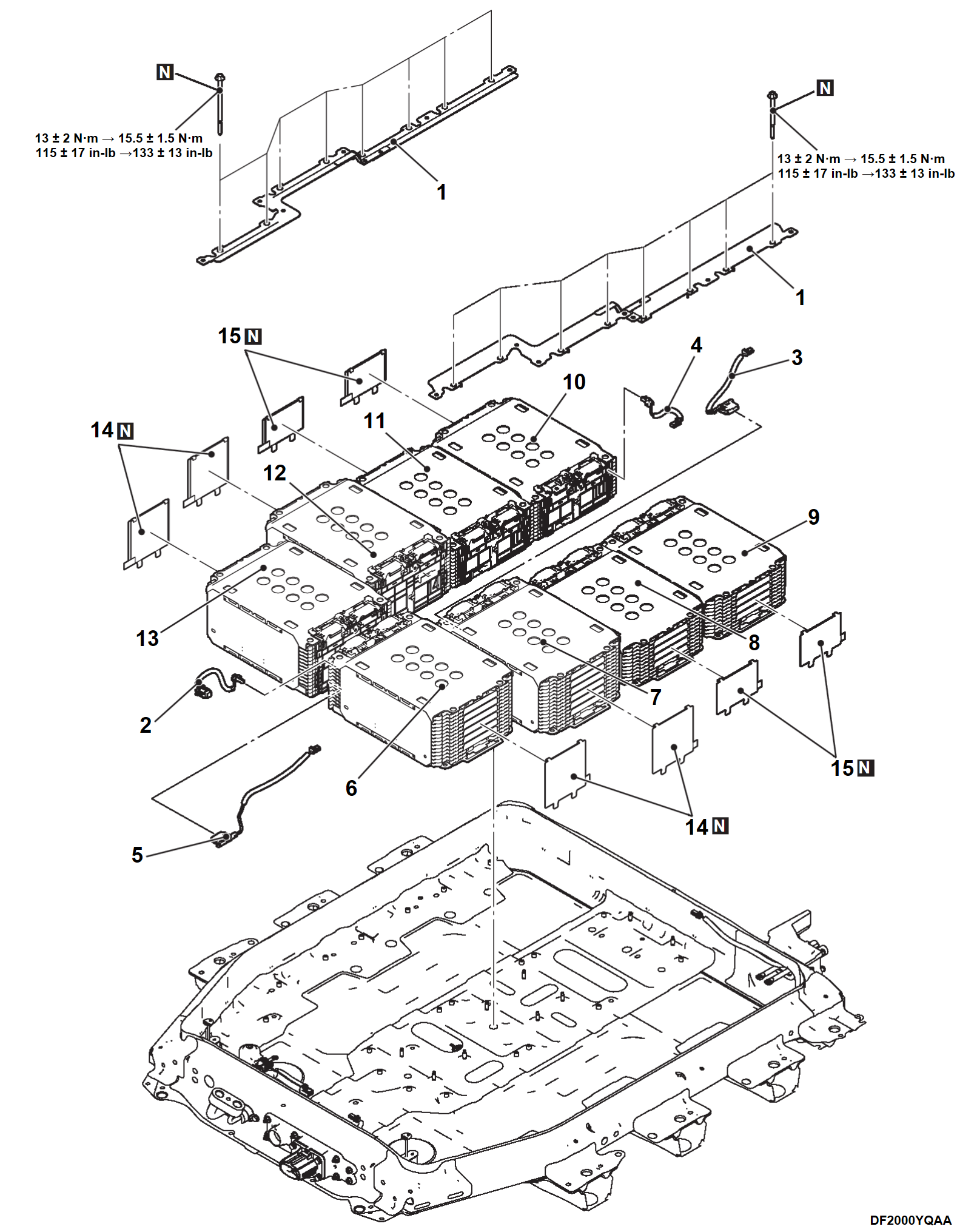
8. BATTERY MODULE REMOVAL AND INSTALLATION
| danger | When servicing the high voltage components, be sure to wear an insulating protective equipment to measure the high voltage (Refer to PRECAUTIONS ON HOW TO USE THE HIGH-VOLTAGE VEHICLE ). ). |
Required Special Tools:
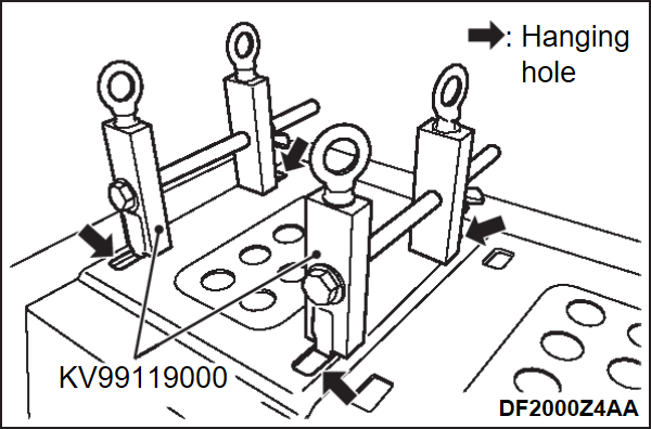
- KV99119000: Module hanger
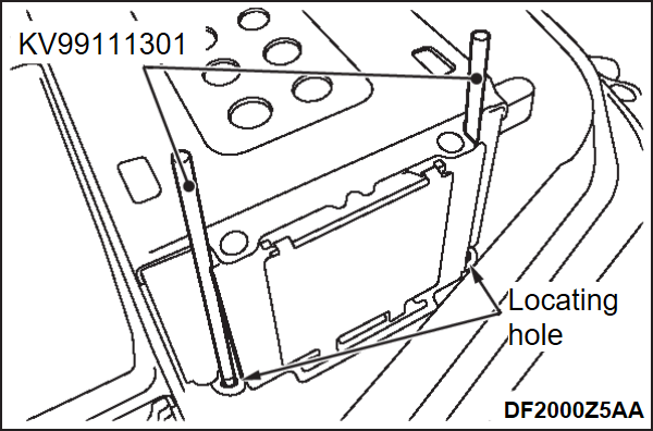
- KV99111301: Locating pin
- MB992915: Electric insulation sheet
REMOVAL SERVICE POINTS
INSTALLATION SERVICE POINTS
<<A>> BATTERY MODULE INSTALLATION
| caution | Do not replace the battery module by itself. |
1. Set the special tool module hanger (KV99119000) on the hanging holes of the battery module as shown in the illustration, and install the battery module.
2. Set the special tool locating pin (KV99111301) to the locating holes at the lower part of the battery module with the taper side down to check that the battery module is placed on the right position.
>>B<< BATTERY HOLDER INSTALLATION
1. Install the battery holder, and temporarily tighten the mounting bolts of the battery holder to the specified torque.
Tightening torque: 13 ± 2 N·m (115 ± 17 in-lb)
2. Fully tighten the mounting bolts of the battery holder to the specified torque.
Tightening torque: 15 ± 1.5 N·m (133 ± 13 in-lb)
![[Previous]](../../../buttons/fprev.png)
![[Next]](../../../buttons/fnext.png)


