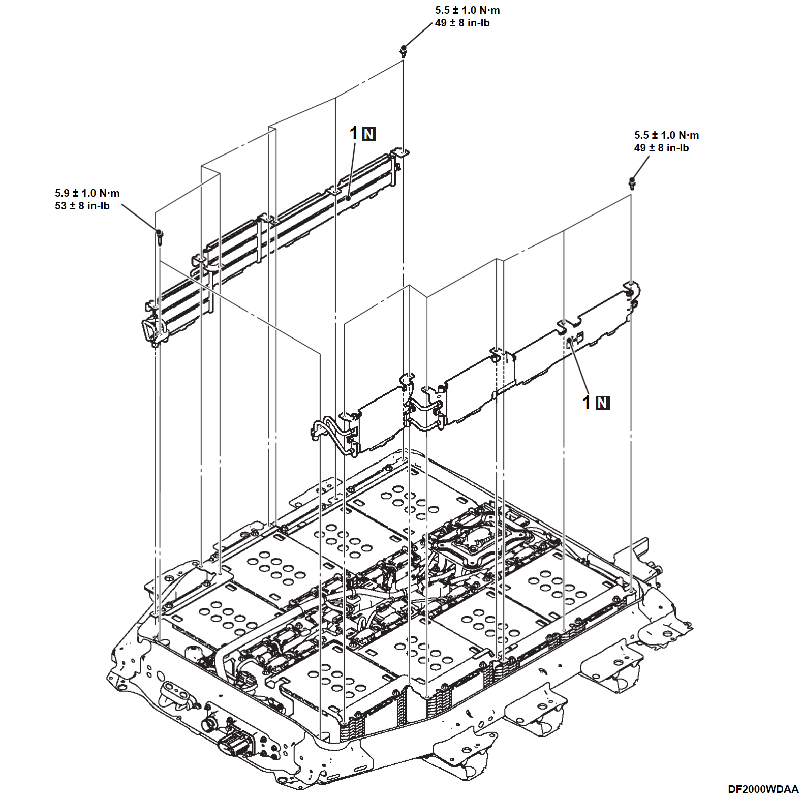
2. DRIVE BATTERY COOLER REMOVAL AND INSTALLATION
| danger | When servicing the high voltage components, be sure to wear an insulating protective equipment to measure the high voltage (Refer to PRECAUTIONS ON HOW TO USE THE HIGH-VOLTAGE VEHICLE ). ). |
Required Special Tools:
- MB993049: Cooling unit installer (for 10 cells module)
- MB993050: Cooling unit installer (for 14 cells module)
- MB992915: Electric insulation sheet
REMOVAL SERVICE POINTS
>>A<< DRIVE BATTERY COOLER ASSEMBLY REMOVAL
1. As there is a risk that foreign materials get inside, cover the piping hole of the drive battery cooler pipe assembly using tape etc. immediately after the drive battery cooler assembly is removed.
2. When the drive battery cooler assembly is removed, replace all the heat sink assemblies on the side from which the heat sink assembly is removed.
INSTALLATION SERVICE POINTS
>>A<< DRIVE BATTERY COOLER ASSEMBLY INSTALLATION
Using the special tool cooling unit installer [MB993049 (for 10-cell battery module installation) and MB993050 (for 14-cell battery module installation)], install the drive battery cooler assembly by the following procedures.
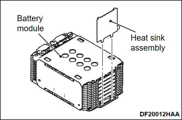
1. Install a new heat sink assembly to the battery module.
2.
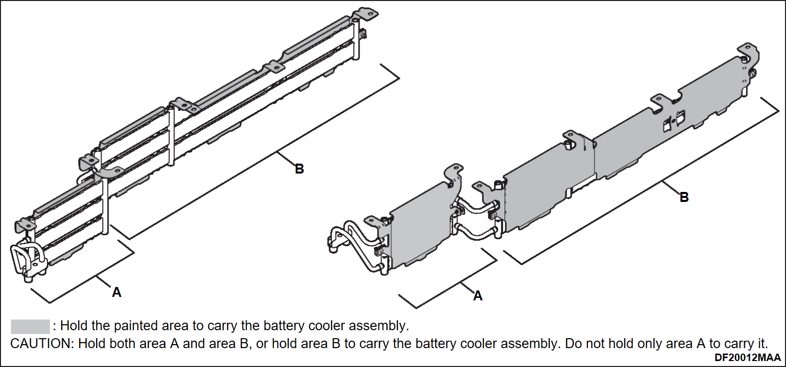
| caution | Do not touch the drive battery cooler assembly surface which contact with the battery module, and piping. |
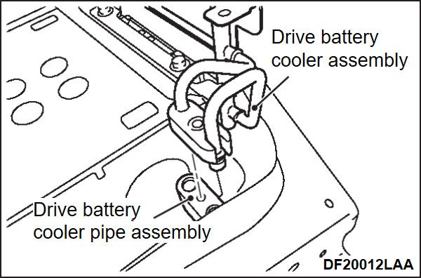
Carry the drive battery cooler assembly so that you do not touch any positions other than those indicated in the illustration.
3.
| caution |
|
Insert the drive battery cooler assembly between the battery module and battery tray, and connect it to the drive battery cooler pipe assembly.
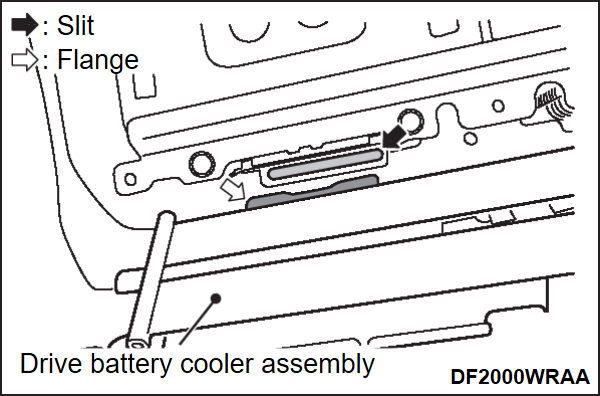
| note | Align the slit for holding the drive battery cooler assembly located on the lower part of the battery module, and the flange of the drive battery cooler assembly. (At this time, do not insert the flange into the slit.) |
4.
| caution |
|
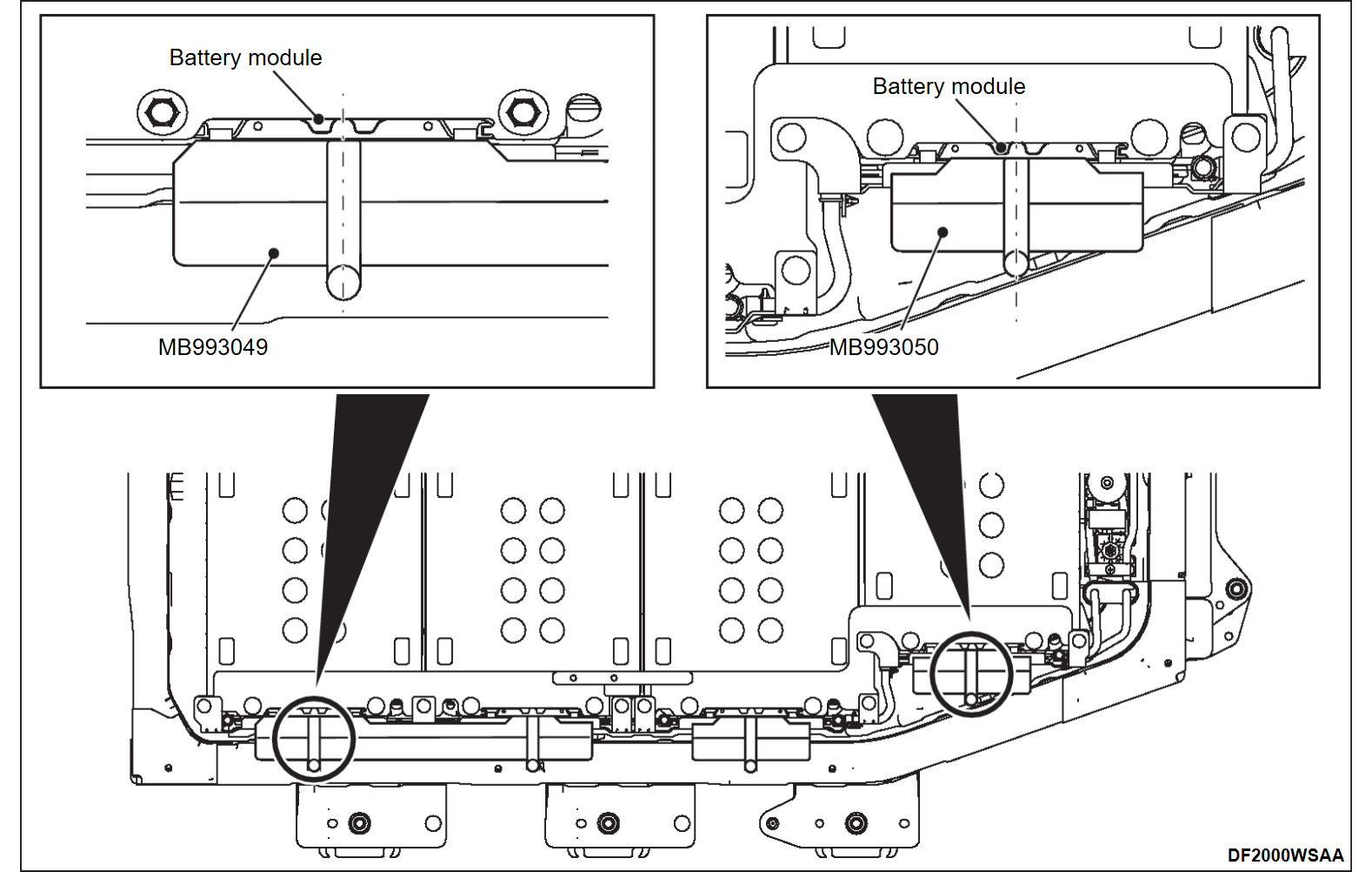
Insert the special tool cooling unit installer [MB993049 (for 10-cell battery module installation) and MB993050 (for 14-cell battery module installation)] between the drive battery cooler assembly and battery tray.
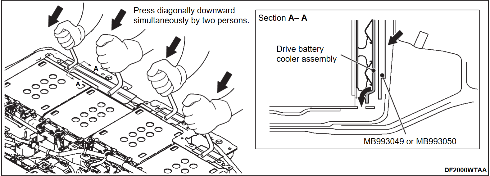
5. Apply pressure to the special tool cooling unit installer [MB993049 (for 10-cell battery module installation) and MB993050 (for 14-cell battery module installation)] diagonally downward to insert the flanges of the drive battery cooler to four slits of the battery modules simultaneously by two persons.
6. While one person is pressing the drive battery cooler assembly against the battery module using the special tool cooling unit installer [MB993049 (for 10-cell battery module installation) and MB993050 (for 14-cell battery module installation)], the other person secures the drive battery cooler assembly with the mounting bolts. Make sure to secure it from the 14-cell battery module side on the vehicle front side in order.
![[Previous]](../../../buttons/fprev.png)
![[Next]](../../../buttons/fnext.png)
