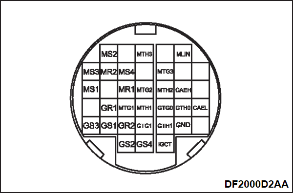
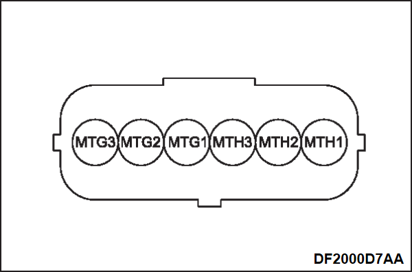
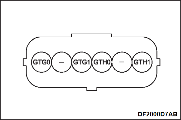
TEMPERATURE SENSOR CIRCUIT INSPECTION
Required Special Tools:
- MB991223: Wiring harness set
- MB992006: Extra fine probe
Front motor U phase coil temperature sensor circuit inspection
1. Disconnect the connector of the power drive unit.
2. Visually check that there is no damage and foreign materials.
3. Disconnect the front motor connector (6 pins).
4. Visually check that there is no damage and foreign materials.
5. With disconnecting the front motor connector (6 pins), check the continuity between the harness side connector terminals of the power drive unit.
| Power drive unit side harness terminal | Standard value | |
| Body ground | MTH1 | No continuity |
| MTG1 | ||
| IGCT | ||
6. Check the harness continuity between the power drive unit and front motor.
| Power drive unit side harness terminal | Front motor side harness terminal | Standard value | ||
| MTH1 | MTH1 | Continuity exists (2 Ω or less) | ||
| MTG1 | MTG1 | |||
7. Connect the front motor connector (6 pins).
8. Check the resistance value between the harness side connector terminals of the power drive unit.
| Power drive unit side harness terminal | Standard value | ||||||
| MTH1 | MTG1 | 59.38 to 69.22 kΩ [at –20°C (-4°F)] | |||||
| 31.78 to 36.11 kΩ [at 0°C (32°F)] | |||||||
| 18.46 to 20.51 kΩ [at 20°C (68°F)] | |||||||
| 11.46 to 12.48 kΩ [at 40°C (104°F)] | |||||||
| Body ground | MTH1 | No continuity | |||||
- If the resistance value is in the standard value range, the front motor U phase coil temperature sensor circuit is normal.
- If the resistance value is not in the standard value range, replace the front motor (refer to MOTOR (ELECTRIC MOTOR UNIT) REMOVAL AND INSTALLATION
 ).
).
Front motor V phase coil temperature sensor circuit inspection
1. Disconnect the connector of the power drive unit.
2. Visually check that there is no damage and foreign materials.
3. Disconnect the front motor connector (6 pins).
4. Visually check that there is no damage and foreign materials.
5. With disconnecting the front motor connector (6 pins), check the continuity between the harness side connector terminals of the power drive unit.
| Power drive unit side harness terminal | Standard value | |
| Body ground | MTH3 | No continuity |
| MTG3 | ||
| IGCT | ||
6. Check the harness continuity between the power drive unit and front motor.
| Power drive unit side harness terminal | Front motor side harness terminal | Standard value | ||
| MTH3 | MTH3 | Continuity exists (2 Ω or less) | ||
| MTG3 | MTG3 | |||
7. Connect the front motor connector (6 pins).
8. Check the resistance value between the harness side connector terminals of the power drive unit.
| Power drive unit side harness terminal | Standard value | ||||||
| MTH3 | MTG3 | 59.38 to 69.22 kΩ [at –20°C (-4°F)] | |||||
| 31.78 to 36.11 kΩ [at 0°C (32°F)] | |||||||
| 18.46 to 20.51 kΩ [at 20°C (68°F)] | |||||||
| 11.46 to 12.48 kΩ [at 40°C (104°F)] | |||||||
| Body ground | MTH3 | No continuity | |||||
- If the resistance value is in the standard value range, the front motor V phase coil temperature sensor circuit is normal.
- If the resistance value is not in the standard value range, replace the front motor (refer to MOTOR (ELECTRIC MOTOR UNIT) REMOVAL AND INSTALLATION
 ).
).
Front motor W phase coil temperature sensor circuit inspection
1. Disconnect the connector of the power drive unit.
2. Visually check that there is no damage and foreign materials.
3. Disconnect the front motor connector (6 pins).
4. Visually check that there is no damage and foreign materials.
5. With disconnecting the front motor connector (6 pins), check the continuity between the harness side connector terminals of the power drive unit.
| Power drive unit side harness terminal | Standard value | |
| Body ground | MTH2 | No continuity |
| MTG2 | ||
| IGCT | ||
6. Check the harness continuity between the power drive unit and front motor.
| Power drive unit side harness terminal | Front motor side harness terminal | Standard value | ||
| MTH2 | MTH2 | Continuity exists (2 Ω or less) | ||
| MTG2 | MTG2 | |||
7. Connect the front motor connector (6 pins).
8. Check the resistance value between the harness side connector terminals of the power drive unit.
| Power drive unit side harness terminal | Standard value | ||||||
| MTH2 | MTG2 | 59.38 to 69.22 kΩ [at –20°C (-4°F)] | |||||
| 31.78 to 36.11 kΩ [at 0°C (32°F)] | |||||||
| 18.46 to 20.51 kΩ [at 20°C (68°F)] | |||||||
| 11.46 to 12.48 kΩ [at 40°C (104°F)] | |||||||
| Body ground | MTH2 | No continuity | |||||
- If the resistance value is in the standard value range, the front motor W phase coil temperature sensor circuit is normal.
- If the resistance value is not in the standard value range, replace the front motor (refer to MOTOR (ELECTRIC MOTOR UNIT) REMOVAL AND INSTALLATION
 ).
).
Generator coil temperature sensor circuit inspection
1. Disconnect the connector of the power drive unit.
2. Visually check that there is no damage and foreign materials.
3. Disconnect the generator connector (6 pins).
4. Visually check that there is no damage and foreign materials.
5. With disconnecting the generator connector (6 pins), check the continuity between the harness side connector terminals of the power drive unit.
| Power drive unit side harness terminal | Standard value | |
| Body ground | GTH1 | No continuity |
| GTG1 | ||
| IGCT | ||
6. Check the harness continuity between the power drive unit and generator.
| Power drive unit side harness terminal | Generator side harness terminal | Standard value | ||
| GTH1 | GTH1 | Continuity exists (2 Ω or less) | ||
| GTG1 | GTG1 | |||
7. Connect the generator connector (6 pins).
8. Check the resistance value between the harness side connector terminals of the power drive unit.
| Power drive unit side harness terminal | Standard value | ||||||
| GTH1 | GTG1 | 59.38 to 69.22 kΩ [at –20°C (-4°F)] | |||||
| 31.78 to 36.11 kΩ [at 0°C (32°F)] | |||||||
| 18.46 to 20.51 kΩ [at 20°C (68°F)] | |||||||
| 11.46 to 12.48 kΩ [at 40°C (104°F)] | |||||||
| Body ground | GTH1 | No continuity | |||||
- If the resistance value is in the standard value range, the generator coil temperature sensor circuit is normal.
- If the resistance value is not in the standard value range, replace the generator (refer to GENERATOR REMOVAL AND INSTALLATION
 ).
).
EV oil cooling system oil temperature sensor circuit inspection
1. Disconnect the connector of the power drive unit.
2. Visually check that there is no damage and foreign materials.
3. Disconnect the generator connector (6 pins).
4. Visually check that there is no damage and foreign materials.
5. With disconnecting the generator connector (6 pins), check the continuity between the harness side connector terminals of the power drive unit.
| Power drive unit side harness terminal | Standard value | |
| Body ground | GTH0 | No continuity |
| GTG0 | ||
| IGCT | ||
6. Check the harness continuity between the power drive unit and generator.
| Power drive unit side harness terminal | Generator side harness terminal | Standard value | ||
| GTH0 | GTH0 | Continuity exists (2 Ω or less) | ||
| GTG0 | GTG0 | |||
7. Connect the generator connector (6 pins).
8. Check the resistance value between the harness side connector terminals of the power drive unit.
| Power drive unit side harness terminal | Standard value | ||||||
| GTH0 | GTG0 | 42.38 to 45.86 kΩ [at –20°C (-4°F)] | |||||
| 23.97 to 25.54 kΩ [at 0°C (32°F)] | |||||||
| 14.30 to 15.08 kΩ [at 20°C (68°F)] | |||||||
| 8.98 to 9.38 kΩ [at 40°C (104°F)] | |||||||
| Body ground | GTH0 | No continuity | |||||
- If the resistance value is in the standard value range, the EV oil cooling system oil temperature sensor circuit is normal.
- If the resistance value is not in the standard value range, replace the generator (refer to GENERATOR REMOVAL AND INSTALLATION
 ).
).
![[Previous]](../../../buttons/fprev.png)
![[Next]](../../../buttons/fnext.png)


