DTC P062F-00: EEPROM malfunction
CIRCUIT OPERATION
- MFI relay is built into the IPDM E/R.
- In the IPDM E/R, the voltage from the 12V battery is applied.
- The ECM connector terminal number 95 turns ON the power transistor in the unit, and the relay turns ON through electricity being supplied to the MFI relay coil.
- When the MFI relay turns ON, 12V battery voltage is supplied from the IPDM E/R to the ECM, the sensor, and the actuator.
TECHNICAL DESCRIPTION
ECM set the information such as the learned value and so on in the memory of ECM.
DESCRIPTIONS OF MONITOR METHODS
To check whether the information such as the learned value and so on is set in the memory of ECM.
MONITOR EXECUTION
Once per driving cycle.
MONITOR EXECUTION CONDITIONS (Other monitor and Sensor)
Other Monitor (There is no temporary DTC set in memory for the item monitored below)
- Not applicable
Sensor (The sensor below is determined to be normal)
- Not applicable
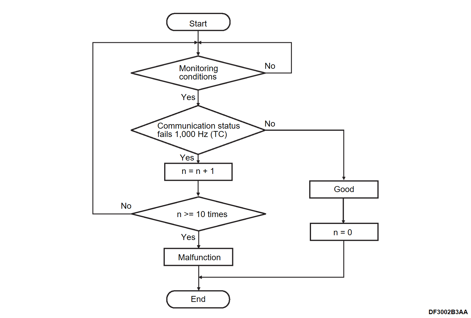
DTC SET CONDITIONS
Check Condition
- Power supply mode of electric motor switch is ON.
Judgment Criterion
- The latest data that was flashed while the power supply mode of the electric motor switch was OFF are not set correctly for 10 times.
FAIL-SAFE AND BACKUP FUNCTION
None.
OBD-II DRIVE CYCLE PATTERN
None.
TROUBLESHOOTING HINTS (The most likely causes for this code to be set are:)
ECM failed.
DIAGNOSIS
Required Special Tools:
- MB992744: Vehicle communication interface-Lite (V.C.I.-Lite)
- MB992745: V.C.I.-Lite main harness A
- MB992747: V.C.I.-Lite USB cable short
- MB992748: V.C.I.-Lite USB cable long
1.STEP 1. Using scan tool (M.U.T.-III SE), DTC recheck after erasing DTC.
After erasing the DTC, check again to see if the DTC is set again. Replace the ECM (Refer to ENGINE CONTROL MODULE (ECM) REMOVAL AND INSTALLATION
 ).
). Intermittent malfunction (Refer to GENERAL INFORMATION, General Information – How to Use Troubleshooting/Inspection Service Points – How to Cope with Intermittent Malfunctions HOW TO COPE WITH INTERMITTENT MALFUNCTIONS
 ).
).
(1) Use scan tool (M.U.T.-III SE) to erase the DTC.
(2) Turn OFF the power supply mode of the electric motor switch.
(3) Turn ON the power supply mode of the electric motor switch.
(4) Use scan tool (M.U.T.-III SE) to recheck the DTC.
Q: Is DTC P062F-00 set?
 Replace the ECM (Refer to ENGINE CONTROL MODULE (ECM) REMOVAL AND INSTALLATION
 ).
). Intermittent malfunction (Refer to GENERAL INFORMATION, General Information – How to Use Troubleshooting/Inspection Service Points – How to Cope with Intermittent Malfunctions HOW TO COPE WITH INTERMITTENT MALFUNCTIONS
 ).
).![[Previous]](../../../buttons/fprev.png)
![[Next]](../../../buttons/fnext.png)
