Diagnosis Procedure
1.CHECK MICROPHONE SIGNAL CIRCUIT AND MICROPHONE POWER SUPPLY CIRCUIT CONTINUITY
- Turn ignition switch OFF.
- Disconnect TCU connector and microphone connector.
- Check continuity between TCU connector and microphone connector.
TCU Microphone Continuity Connector Terminal Connector Terminal M35 17 R8 8 Existed 18 3 - Check the continuity between TCU connector and ground.
TCU Ground Continuity Connector Terminal M35 18 Not existed 17
Is the inspection result normal?
 Repair or replace harness or connectors.
2.CHECK MICROPHONE POWER SUPPLY VOLTAGE
- Connect TCU connector and microphone connector.
- Turn ignition switch ON.
- Check voltage between TCU connector and ground.
(+) (−) Voltage (Approx.)TCU Connector Terminal M35 18 Ground 5.0 V
Is the inspection result normal?
 Replace TCU. Refer to Removal & Installation
 .
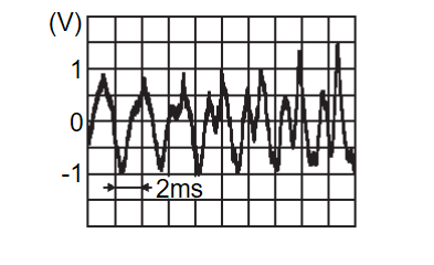
.3.CHECK MICROPHONE SIGNAL
Check signal between TCU connector and ground. Replace TCU.Refer to Removal & Installation
 .
. Replace microphone.Refer to Removal and Installation
 .
.
Is the inspection result normal?
 Replace TCU.Refer to Removal & Installation
 .
. Replace microphone.Refer to Removal and Installation
 .
.![[Previous]](../../../buttons/fprev.png)
![[Next]](../../../buttons/fnext.png)
