Diagnosis Procedure
1.CHECK LIN COMMUNICATION SIGNAL 1
 M.U.T.-III SE DATA MONITOR
Select “Battery current sen value (LIN)” of “IPDM E/R” data monitor item.
| Monitor item | Condition | Monitor status |
| Battery current sen value (LIN) | Engine running
| (–200.00) – (+300.00) A |
Is the inspection result normal?
 Replace IPDM E/R. Refer to Removal and Installation
 .
.2.CHECK FUSE
- Ignition switch OFF.
- Check that the following fuse is not blown (open).
No. Capacity 89 10A
Is the fuse blown (open)?
 Replace the blown (open) fuse after repairing the cause of blown (open).
3.CHECK 12V BATTERY CURRENT SENSOR POWER
- Disconnect 12V battery current sensor connector.
- Ignition switch ON.
- Check the voltage between 12V battery current sensor harness connector and ground.
(+) (-) Voltage (V) 12V battery current sensor Connector Terminal F37 1 Ground 12V battery voltage
Is the inspection result normal?
 Repair or replace harness.
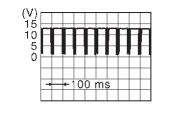
4.CHECK LIN COMMUNICATION SIGNAL
- Ignition switch ON.
- Check signal between 12V battery current sensor harness connector and ground using an oscilloscope.
Is the inspection result normal?
 Repair or replace harness.
 Replace 12V battery current sensor.
![[Previous]](../../../buttons/fprev.png)
![[Next]](../../../buttons/fnext.png)
