System Description
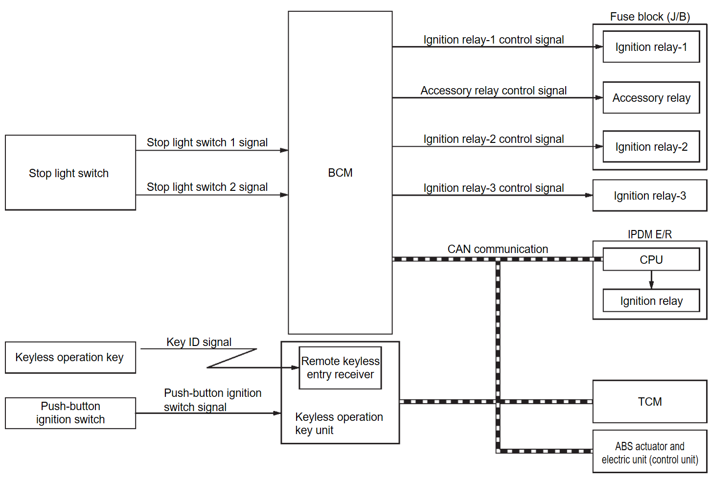
SYSTEM DIAGRAM
| Component | Function |
| Keyless operation key | Operates based on the results of electronic ID verification using two-way communication between the Keyless operation key and the vehicle (Keyless operation key unit). |
| Push-button ignition switch | Refer to Push-button Ignition Switch . . |
| Stop light switch | Stop light switch detects that brake pedal is depressed, and then transmits ON/OFF signal to BCM. |
| TCM | Transmits shift position signal and cranking enable signal to BCM via CAN communication. |
| Keyless operation key unit | Transmits push-button ignition switch status signal to BCM via CAN communication. |
| ABS actuator and electric unit (control unit) | Transmits vehicle speed signal to BCM via CAN communication. |
| BCM |
|
| Ignition relay-1 | Controlled by BCM and turns ON/OFF the battery power supply to each parts. |
| Accessory relay | |
| Ignition relay-2 | |
| Ignition relay-3 | |
| IPDM E/R | IPDM E/R controls the integrated ignition relay, and supplies voltage to the load according to the request from BCM via CAN communication. |
SYSTEM DESCRIPTION
- POWER DISTRIBUTION SYSTEM is the system that BCM controls with the operation of push-button ignition switch and performs the power distribution to each power circuit. This system is used instead of the mechanical power supply changing mechanism with the operation of the conventional key cylinder.Allocation to the accessory power supply, refer to the auto ACC function. Refer to System Description
 .
. - Push-button ignition switch can be operated when Keyless operation key is in the following condition.
- Keyless operation key is in the detection area of the inside key antenna.
- Keyless operation key backside is contacted to push-button ignition switch.
- Push-button ignition switch operation is input to Keyless operation key unit as a signal. Keyless operation key unit transmits push-button ignition switch status signal to BCM via CAN communication. BCM changes the ignition switch position according to the status and operates the following relays to supply power to each power circuit.
- Ignition relay (built-in IPDM E/R)
- Ignition relay-1 [installed in fuse block (J/B)]
- Ignition relay-2 [installed in fuse block (J/B)]
- Ignition relay-3 (installed in relay holder)
note Ignition relay-3 turns ON only when the engine is running. - Accessory relay[installed in fuse block (J/B)]
IGNITION BATTERY SAVER SYSTEM
Ignition battery saver system is a system in which the BCM automatically shuts off the power supply (ignition switch position ON -> OFF) to protect the battery.
BCM activates ignition battery saver system 10 minutes after ignition battery saver timer function operating conditions are met.
Operating Condition of Ignition Battery Saver Timer Function
When all the following conditions are met for a 10 minutes, the battery saver system will cut off the power supply (ignition switch position ON -> OFF) to prevent battery discharge.
- Ignition switch is in the ON position
- Engine stopped
Cancel Condition of Ignition Battery Saver Timer Function
If any of the following conditions are met the battery saver timer function is canceled.
- Ignition switch is not in the ON position
- Engine running
- M.U.T.-III SE is connected
note - Ignition battery saver timer function will return 1 minute or more, after closing M.U.T.-III SE or removing VI from the vehicle.
- When ignition battery saver is disabling, the operation of push-button ignition switch less than 2 seconds is not accepted.
- To resume ignition battery saver system, press and hold the push-button ignition switch continuously for 3 seconds or more with the brake pedal is not depressed. (Ignition switch turns ON -> OFF)
IGNITION SWITCH POSITION CHANGE TABLE BY PUSH-BUTTON IGNITION SWITCH OPERATION
Refer to System Description .
.
 .
.![[Previous]](../../../buttons/fprev.png)
![[Next]](../../../buttons/fnext.png)
