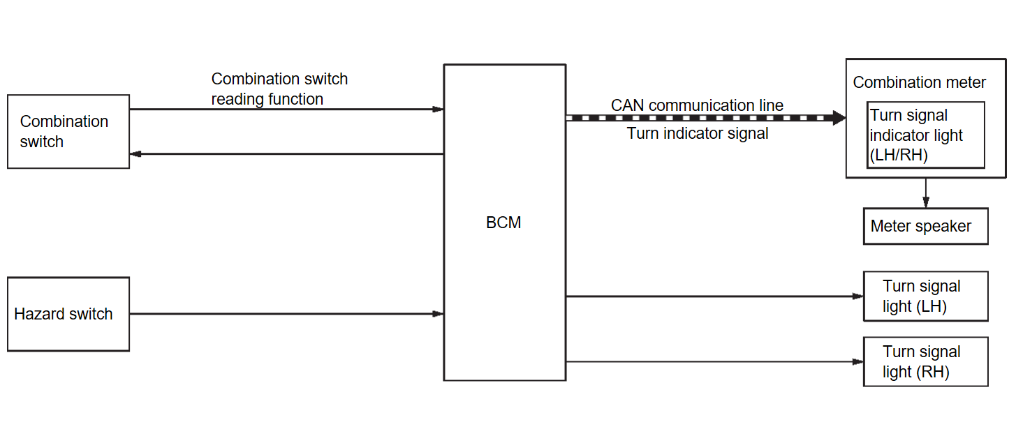
System Description
SYSTEM DIAGRAM
| Component | Function | |
| Front combination light | Front turn signal light |
|
| Door mirror | Side turn signal light* |
|
| Rear combination light (body side) | Rear turn signal light |
|
| Hazard switch | Refer to Hazard Switch . . | |
| BCM |
| |
| Combination meter | Blinks the turn signal indicator light and outputs the turn signal operating sound to meter speaker according to the status from BCM via CAN communication. | |
| Meter speaker | Outputs the turn signal operating sound according to the signal from combination meter. | |
| Combination switch | Lighting & turn signal switch | Inputs the each switch condition signal to BCM. |
*: With side turn signal light
OUTLINE
Turn signal light and hazard warning light is controlled by combination switch reading function and the flasher control function of BCM.
TURN SIGNAL LIGHT OPERATION
- BCM detects the combination switch condition by the combination switch reading function.
- BCM supplies voltage to the right (left) turn signal light circuit when the ignition switch is ON and the turn signal switch is in the right (left) position. BCM blinks the turn signal light.
HAZARD WARNING LIGHT OPERATION
BCM supplies voltage to both turn signal light circuits when the hazard switch is ON. BCM blinks the hazard warning light.
TURN SIGNAL INDICATOR LIGHT AND TURN SIGNAL SOUND OPERATION
- BCM transmits the turn indicator signal to the combination meter via CAN communication while the turn signal light and the hazard warning light are operating.
- Combination meter outputs the turn signal sound to the meter speaker while blinking the turn signal indicator light according to the turn indicator signal.
- Meter speaker outputs the turn signal sound according to the signal from combination meter.
3-TIME FLASHER FUNCTION
- By a short touch of the turn signal lever, BCM blinks the turn signal lamps 3 times in the selected direction.
- Cancels the operation when short touch of the turn signal lever in the reverse direction during the 3-time flasher function operation.
| note | The flasher setting of 3-time flasher function can be changed using M.U.T.-III SE. Refer to M.U.T.-III SE Function (BCM - BCM)CONSULT Function (BCM - BCM) . . |
HIGH FLASHER OPERATION
- BCM detects the turn signal light circuit status from the current value.
- BCM increases the turn signal light blinking speed if the light or harness open is detected with the turn signal light operating.
note The blinking speed is normal while operating the hazard warning light.
![[Previous]](../../../buttons/fprev.png)
![[Next]](../../../buttons/fnext.png)
