Removal and Installation
REMOVAL
1. Remove tires. Refer to Removal & Installation .
.
 .
.2. Remove wheel sensor from wheel hub and bearing assembly. Refer to Removal and Installation .
.
 .
.3. Remove caliper assembly. Hang caliper assembly in a place where it will not interfere with work. Refer to Removal and Installation .
.
 .
.| caution | Never depress brake pedal while brake caliper is removed. |
4. Remove disc rotor. If disc rotor cannot be removed, remove as follows.
| caution |
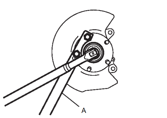
5. Remove cotter pin, and then loosen wheel hub lock nut, using a wheel hub lock nut wrench (A) (SST: KV40104000).
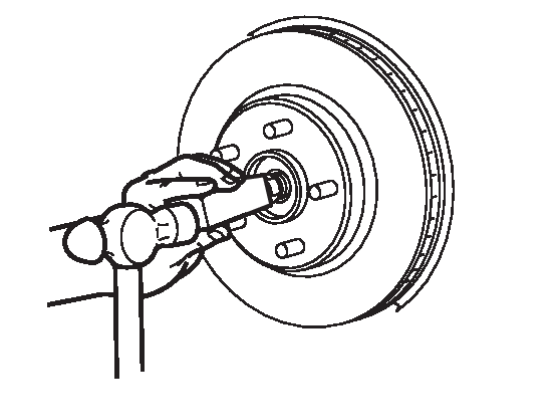
6. Patch hub lock nut with a piece of wood. Hammer the wood to disengage wheel hub and bearing assembly from drive shaft.
| note | Use suitable puller, if wheel hub and bearing assembly and drive shaft cannot be separated even after performing the above procedure. |
7. Remove wheel hub and bearing assembly.
| caution | Remove parking brake assembly only when necessary. |
8. Remove back plate.
9. Remove hub cap.
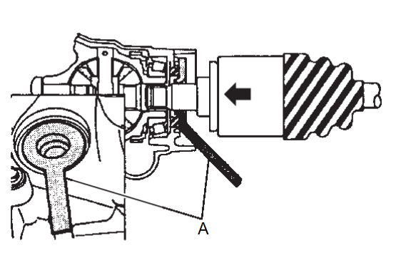
10. Remove the rear drive shaft from the rear final drive.
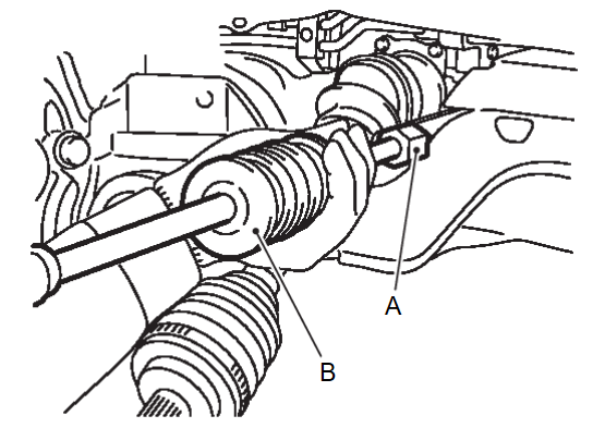
- Use the drive shaft attachment (A) (SST: KV40107500) and a sliding hammer (B) while inserting tip of the drive shaft attachment between housing and final drive assembly.
caution - Never place drive shaft joint at an extreme angle when removing drive shaft. Also be careful not to overextend slide joint.
- Confirm that the circular clip is attached to the drive shaft.
11. Perform inspection after removal. Refer to Inspection .
.
 .
.INSTALLATION
Note the following, and install in the reverse order of removal.
| caution | Always replace side oil seal with new one when installing drive shaft. Refer to Exploded ViewRemoval and Installation . . |
- Place the protector (A) (SST: KV38107900) onto final drive assembly to prevent damage to the side oil seal while inserting drive shaft. Slide drive shaft sliding joint and tap with a hammer to install securely.
caution - Check that circular clip is completely engaged.
- Never reuse side oil seal.
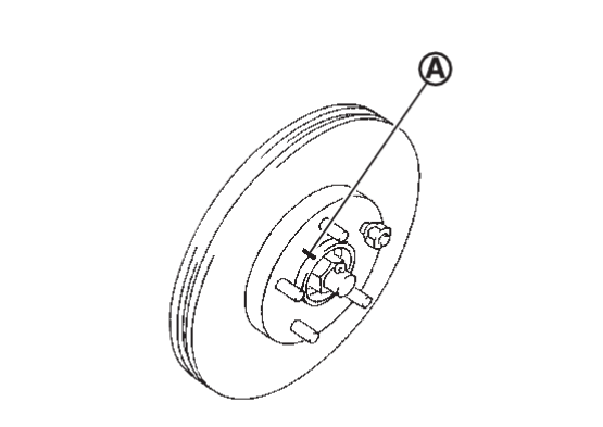
- Align the matching marks
 made during removal when reusing the disc rotor.
 - Perform final tightening of bolts and nuts at suspension arm (rubber bushing), under unladen conditions with tires on level ground.
- Tighten the wheel hub lock nut to the specified torque. Refer to Exploded View
 .
. - Perform inspection after installation. Refer to Inspection
 .
.
![[Previous]](../../../buttons/fprev.png)
![[Next]](../../../buttons/fnext.png)
