Diagnosis Procedure
1.CHECK MODE DOOR MOTOR POWER SUPPLY
- Ignition switch ON.
- Check voltage between mode door motor harness connector and A/C amp. harness connector.
| + | − | Voltage | ||
| Mode door motor | A/C amp. | |||
| Connector | Terminal | Connector | Terminal | |
| M143 | 1 | M55 | 58 | 10.5 – 16 V |
Is the inspection result normal?
2.CHECK MODE DOOR MOTOR GROUND CIRCUIT FOR OPEN
- Ignition switch OFF.
- Disconnect mode door motor connector and A/C amp. connector.
- Check continuity between mode door motor harness connector and A/C amp. harness connector.
Mode door motor A/C amp. Continuity Connector Terminal Connector Terminal M143 2 M54 27 Existed
Is the inspection result normal?
 Repair harness or connector.
3.CHECK MODE DOOR MOTOR LIN SIGNAL CIRCUIT
- Connect mode door motor connector and A/C amp. connector.
- Ignition switch ON.
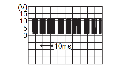
- Confirm output waveform between mode door motor harness connector and A/C amp. harness connector with oscilloscope.
Is the inspection result normal?
 Replace mode door motor. Refer to Removal and Installation
 .
.4.CHECK MODE DOOR MOTOR POWER SUPPLY CIRCUIT FOR OPEN
- Ignition switch OFF.
- Disconnect mode door motor connector and A/C amp. connector.
- Check continuity between mode door motor harness connector and A/C amp. harness connector.
Mode door motor A/C amp. Continuity Connector Terminal Connector Terminal M143 1 M54 1 Existed
Is the inspection result normal?
 Repair harness or connector.
5.CHECK MODE DOOR MOTOR POWER SUPPLY CIRCUIT FOR SHORT
- Disconnect following connectors.
- Air mix door motor LH
- Air mix door motor RH
- Air mix door motor (rear)
- Intake door motor
- Check continuity between mode door motor harness connector and ground.
Mode door motor — Continuity Connector Terminal M143 1 Ground Not existed
Is the inspection result normal?
 Replace A/C amp. Refer to Removal and Installation
 .
. Repair harness or connector.
6.CHECK MODE DOOR MOTOR LIN SIGNAL CIRCUIT FOR OPEN
- Ignition switch OFF.
- Disconnect mode door motor connector and A/C amp. connector.
- Check continuity between mode door motor harness connector and A/C amp. harness connector.
Mode door motor A/C amp. Continuity Connector Terminal Connector Terminal M143 3 M54 2 Existed
Is the inspection result normal?
 Repair harness or connector.
7.CHECK MODE DOOR MOTOR LIN SIGNAL CIRCUIT FOR SHORT
- Disconnect following connectors.
- Air mix door motor LH
- Air mix door motor RH
- Air mix door motor (rear)
- Intake door motor
- Check continuity between mode door motor harness connector and ground.
Mode door motor — Continuity Connector Terminal M143 3 Ground Not existed
Is the inspection result normal?
 Replace A/C amp. Refer to Removal and Installation
 .
. Repair harness or connector.
![[Previous]](../../../buttons/fprev.png)
![[Next]](../../../buttons/fnext.png)
