Removal and Installation
REMOVAL
| note | When removing components such as hoses, tubes/lines, etc., cap or plug openings to prevent fluid from spilling. |
1. Remove air cleaner cover and air cleaner body. Refer to Removal and Installation .
.
 .
.2. Remove engine under cover. Refer to Exploded View .
.
 .
.3. Release hose clamps.
4. Remove CVT fluid cooler hose A and CVT fluid cooler hose B from radiator.
5. Remove CVT fluid cooler hose A and CVT fluid cooler hose B from CVT oil warmer.
INSTALLATION
Note the following, and install in the reverse order of removal.
| caution |
|
*Refer to the following when installing CVT fluid cooler hoses
| Hose name (1) | Installation side tube (2) | Direction of paint mark | Hose insertion depth (L) |
| CVT fluid cooler hose A | CVT oil warmer | Marking of the CVT oil warmer |  : End reaches the CVT oil warmer. : End reaches the CVT oil warmer. |
| Radiator | Leftward |  : End reaches the radiator. : End reaches the radiator. | |
| CVT fluid cooler hose B | Radiator | Leftward | |
| CVT oil warmer | Frontward |  : End reaches the 2–step bulge : End reaches the 2–step bulge |
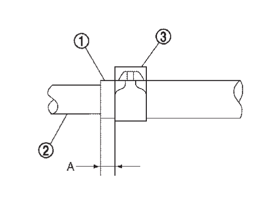
*Refer to the following when installing hose clamps
| Hose name (1) | Installation side tube (2) | Hose clamp (3) | |
| Direction of tab | Clamping position (A) | ||
| CVT fluid cooler hose A | CVT oil warmer | Marking of the CVT oil warmer | 2 - 5 mm (0.08 - 0.20 in) from hose end |
| Radiator | Leftward | ||
| CVT fluid cooler hose B | CVT oil warmer | Frontward | |
| Radiator | Leftward | ||
Adjust the CVT fluid level. Refer to Adjustment .
.
 .
.![[Previous]](../../../buttons/fprev.png)
![[Next]](../../../buttons/fnext.png)

