Disassembly and Assembly
DISASSEMBLY
1. Mount the engine on a suitable engine stand. Refer to Setting.Setting

2. Drain any remaining engine oil and engine coolant if necessary.
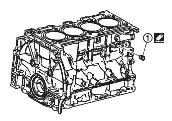
3. Remove drain plugs from cylinder block.
4. Remove cylinder head. Refer to Removal and Installation.Removal and Installation

5. Remove oil pan (upper). Refer to Removal and Installation.Removal and Installation

6. Remove the thermostat housing. Refer to Removal and Installation.Removal and Installation

7. Remove knock sensors.
| caution | Carefully handle knock sensor avoiding shocks. |
8. Remove crankshaft position sensor.
| caution |
|
9. Remove piston and connecting rod assembly with the following procedure:
- Before removing piston and connecting rod assembly, check the connecting rod side clearance. Refer to Inspection
 .
.
(1) Position crankshaft pin corresponding to connecting rod to be removed onto the bottom dead center.
(2) Remove connecting rod cap. Number connecting rod caps so they can be assembled in the same position and direction.
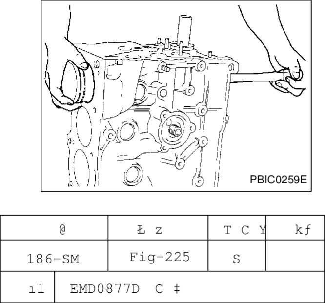
(3) Using a suitable tool, push piston and connecting rod assembly out to cylinder head side.
| caution |
|
| note | Number the pistons and rods so they can be installed in the same position. |
10. Remove connecting rod bearings.
| caution | When removing them note the installation position. Keep them in the correct order. |
11. Remove piston rings from piston.
- Before removing piston rings check the piston ring side clearance. Refer to Inspection
 .
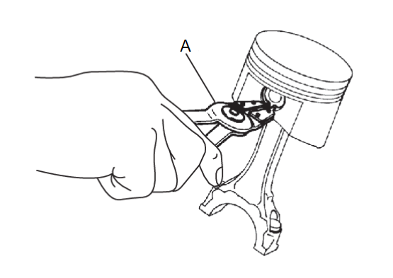
. - Remove piston rings using suitable tool (A).
caution - When removing piston rings, do not damage the piston.
- Do not damage piston rings by expanding them excessively.
12. Remove piston from connecting rod using the following procedure:
13. Remove ladder assembly using the following procedure:
- Measure crankshaft end play before loosening ladder assembly bolts. Refer to Inspection
 .
.
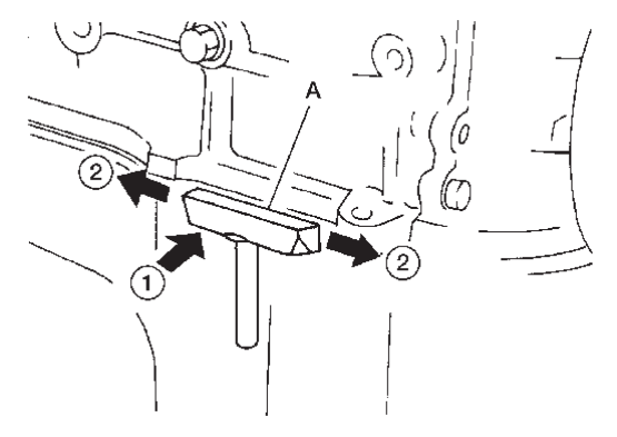
(2) Remove the ladder assembly using seal cutter [KV10111100 (J-37228)] (A).
| caution | Do not damage the mating surfaces. |
| note | In areas where the cutter is difficult to use, use a plastic hammer to lightly tap  the cutter where the liquid gasket is applied. Use a plastic hammer to slide the cutter where the liquid gasket is applied. Use a plastic hammer to slide  the cutter by tapping on the side. the cutter by tapping on the side. |
(3) Remove the ladder assembly while tapping lightly with a plastic hammer.
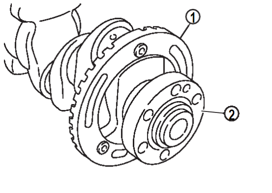
14. Remove crankshaft  .
.
 .
.| caution |
|
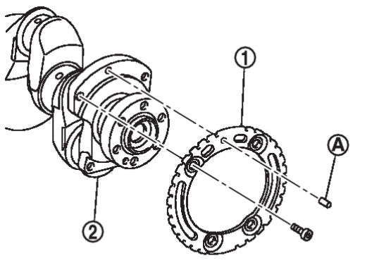
| note | When removing or installing signal plate, use socket (size T30). |
15. Remove main bearing (upper and lower) and thrust bearings from cylinder block and ladder assembly.
| caution | When removing bearings note the installation position. Keep them in the correct order. |
| note | When removing the rear oil seal without removing the cylinder block, use a suitable tool to pull it out between the crankshaft and block. |
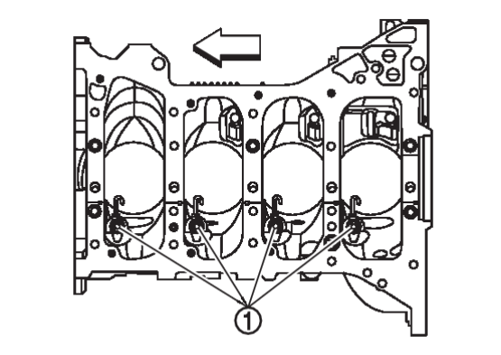
16. Remove oil jets  from cylinder block (if necessary).
 from cylinder block (if necessary).
| caution | When removing oil jet assemblies note the installation position. Keep them in the correct order. |
 | : Engine front |
17. Inspect dowel pins, welch plugs and threaded plugs and remove if necessary.
ASSEMBLY
1. Thoroughly clean engine coolant and oil passages in cylinder block, as well as inside of crankcase and cylinder bores, with compressed air.
| caution | Be sure to wear protective goggles for protection from flying substances. |
2. Install drain plug to cylinder block as shown.
- Apply liquid gasket to the threads of drain plug
 .Use Genuine RTV Silicone Sealant or an equivalent. Refer to Recommended Chemical Products and SealantsRecommended Chemical Products and Sealants
 .
.Water drain plug : 9.8 N·m (1.0 kg-m, 87 in-lb)
4. Install main bearings and thrust bearings using following procedure:
(1) Remove dust, dirt, and engine oil on the bearing mating surfaces of cylinder block and ladder assembly.
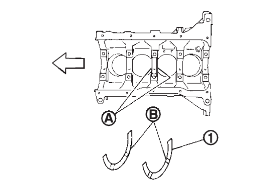
(2) Install thrust bearings  to both sides of the No. 3 journal
  housing on cylinder block.
 to both sides of the No. 3 journal
  housing on cylinder block.
 | : Engine front |
- Install thrust bearings with the oil groove
 facing crankshaft arm (outside).
(3) Install the main bearings paying attention to the direction.
- Before installing bearing, lubricate bearing surface (inside) with clean engine oil.
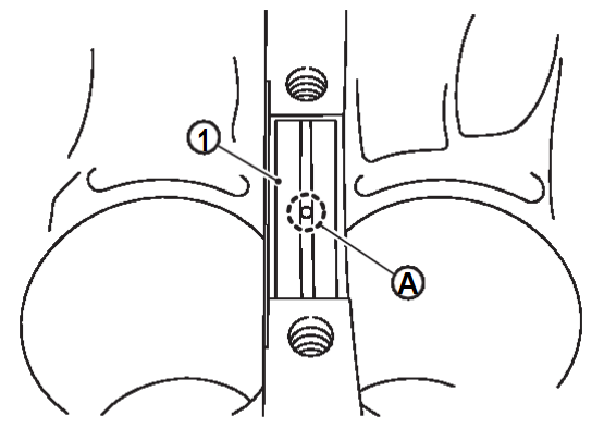
caution Do not apply engine oil to back surface of main bearings. - Check that the oil hole in cylinder block and the oil hole
 in main bearing
  are aligned. The main bearing without an oil hole goes in ladder assembly.
 - When installing, align main bearing stopper to the notch.
- Ensure the oil holes on cylinder block and those on the corresponding bearing are aligned.
5. Install signal plate to crankshaft (if removed).
(1) Set the signal plate with flange facing toward the counterweight side (engine front side).
(3) Remove dowel pin.
| caution | Be sure to remove dowel pin. |
6. Install crankshaft to cylinder block.
- While turning crankshaft by hand, check that it turns smoothly.
| caution | Do not install rear oil seal yet. |
7. Install ladder assembly with the following procedure:
| note | Ladder assembly cannot be replaced as a single part because it is machined together with cylinder block. |
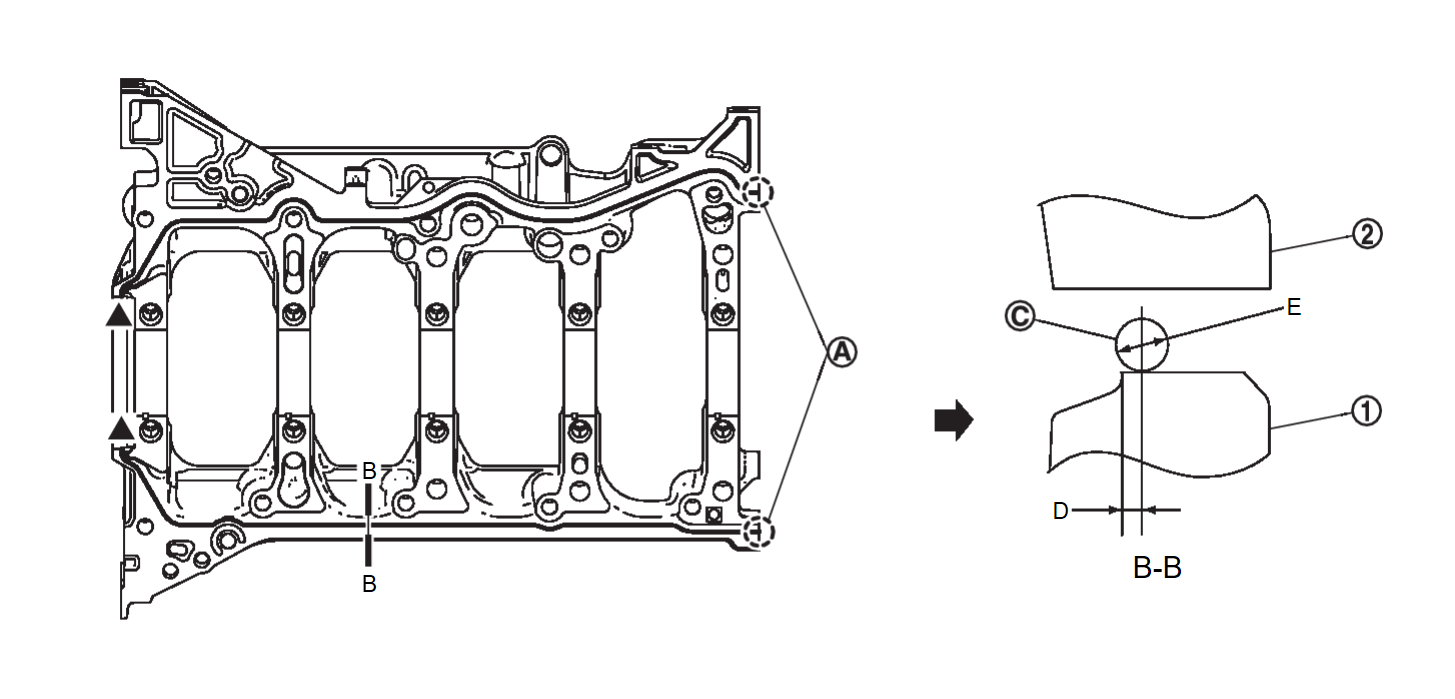
(1) Apply a bead  of liquid gasket with a suitable tool to ladder assembly
  as shown.
 of liquid gasket with a suitable tool to ladder assembly
  as shown.
 | note | After tightening ladder assembly, remove liquid gasket that protrudes at location ( ) shown. ) shown. |
 | : Cylinder block |
 | : Apply liquid gasket to end |
| B | : View B |
| D | : 1.5 mm (0.059 in) |
| E | : 3.4 - 4.4 mm (0.134 - 0.173 in) |
 | : Engine outside |
Use Genuine RTV Silicone Sealant or equivalent. Refer toRecommended Chemical Products and SealantsRecommended Chemical Products and Sealants .
.
 .
.(2) Apply new engine oil to threads and seat surfaces of the bolts.
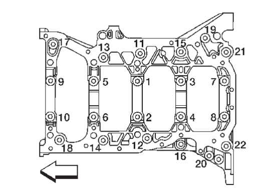
(3) Tighten ladder assembly bolts to specified torque in the sequence shown.
| Step 1 | Bolts 1 – 10 | : 39.2 N·m (4.0 kg-m, 29 ft-lb) |
| Step 2 | Bolts 11 – 22 | : 25.1 N·m (2.6 kg-m, 19 ft-lb) |
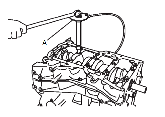
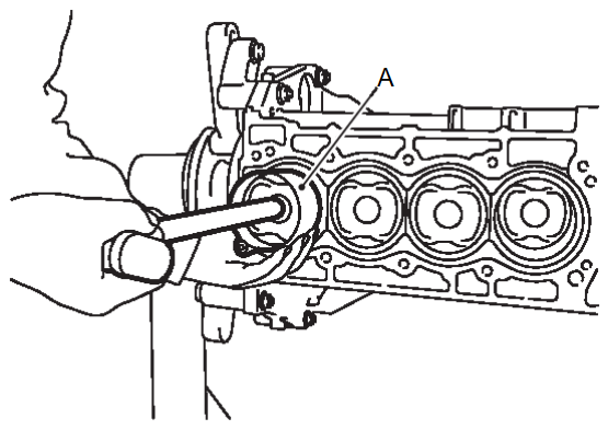
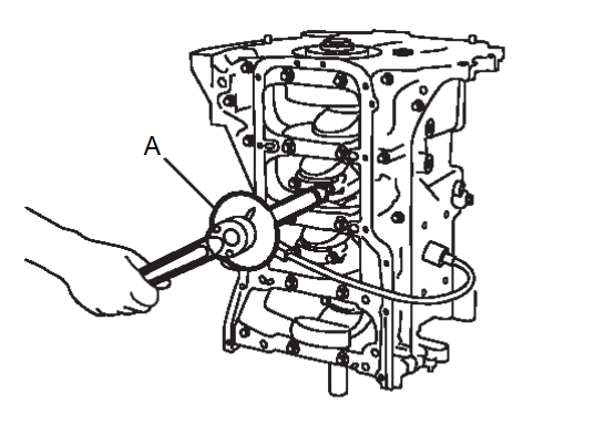
(4) Tighten bolts to specified in the sequence shown using angle wrench [KV10112100 (BT-8653-A)] (A).
| caution | Check tightening angle. Do not judge angle by visual inspection. |
| Bolts 1 – 22 | : 60° – 65° |
(5) Install rear oil seal. Refer to Removal and Installation.Removal and Installation

8. Install piston to connecting rod with the following procedure:
(1) Install new snap ring to the groove of the piston rear side using snap ring pliers.
- Insert it fully into groove to install.
| caution | Do not reuse snap rings. |
(2) Assemble piston to connecting rod.
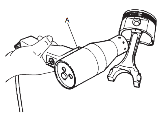
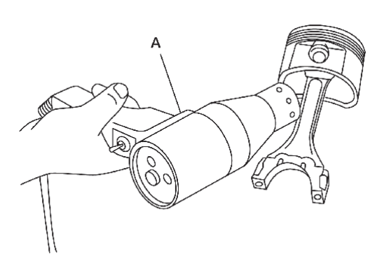
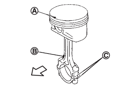
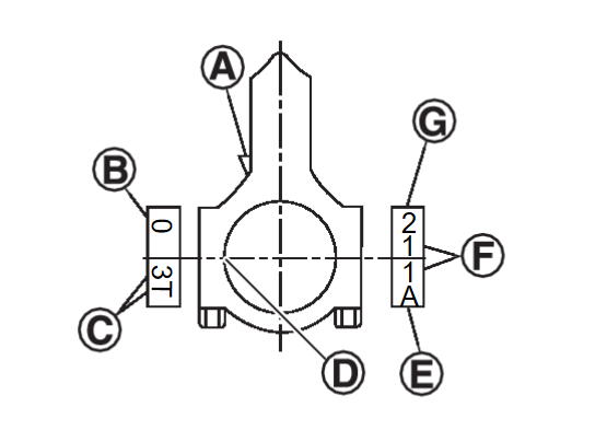
- Using a heat gun (A), heat piston until piston pin can be pushed in by hand without excess force [approximately 60°C to 70°C (140°F to 158°F)]. From the front to the rear, insert piston pin into piston and connecting rod.
- Set so that the front mark
 on the piston head, the oil splash
  and the cylinder number
  on connecting rod are positioned as shown.
(3) Install new snap ring to the groove of the piston front side.
- Insert it fully into groove to install.
- After installing, check that connecting rod moves smoothly.
9. Install piston rings using suitable tool.
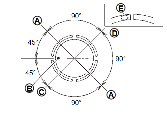
- Position each ring with the gap as shown referring to the piston front mark
 .
.
: Oil ring upper or lower rail gap (either of them) 
: Second ring and oil ring spacer gap 
: Top ring gap - Install second ring with the stamped surface
 facing upward.
| caution |
|
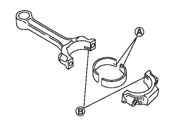
10. Install connecting rod bearings to connecting rod and connecting rod cap.
- When installing connecting rod bearings apply new engine oil to the bearing surface (inside).
caution Do not apply engine oil to the back surface of connecting rod bearings. - When installing, align the connecting rod bearing stopper protrusion
 with the cutout
  of connecting rod and connecting rod cap to install.
 - Ensure the oil hole on connecting rod and that on the corresponding bearing are aligned.
11. Install piston and connecting rod assembly to crankshaft.
- Position crankshaft pin corresponding to connecting rod to be installed onto the bottom dead center.
- Apply new engine oil sufficiently to the cylinder bore, piston and crankshaft pin.
- Match the cylinder position with the cylinder number on connecting rod to install.
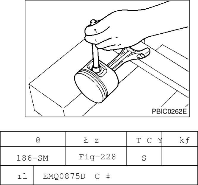
- Using a suitable tool (A), install piston with the front mark on the piston head facing the front of the engine.
caution Do not damage the cylinder wall and crankshaft pin, resulting from an interference of the connecting rod big end.
12. Install connecting rod cap.
13. Tighten connecting rod bolts using angle wrench [KV10112100 (BT-8653-A)] (A) with the following procedure:
(1) Apply engine oil to the threads and seats of the connecting rod bolts.
(2) Tighten connecting rod cap bolts to the specified torque.
| Step 1 | : Tighten 27.4 N·m (2.8 kg-m, 20 ft-lb) |
| Step 2 | : Loosen 0 N·m |
| Step 3 | : 19.6 N·m (2.0 kg-m, 14 lb-ft) |
(3) Tighten connecting rod cap bolts to the specified angle.
| caution | Check tightening angle. Do not judge angle by visual inspection. |
| Bolts | : Tighten 90° - 95° |
(4) After tightening connecting rod bolts, check that crankshaft rotates smoothly.
(5) Check the connecting rod side clearance. Refer to Inspection .
.
 .
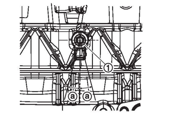
.14. Install knock sensors  .
.
 .
.- Install knock sensor with connector facing +/- 15°
 as shown.
| caution |
|
| note |
|
15. Install crankshaft position sensor (POS).
| caution | Do not reuse O-ring. |
16. Assembly of remaining components is in the reverse order of disassembly.
If replacing or removing piston, connecting rod or crankshaft perform "Electric intake valve timing control actuator position learning". Refer to Work Procedure .
.
 .
.![[Previous]](../../../buttons/fprev.png)
![[Next]](../../../buttons/fnext.png)
