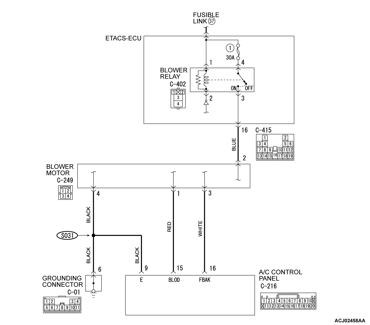
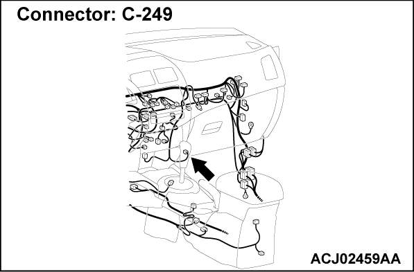
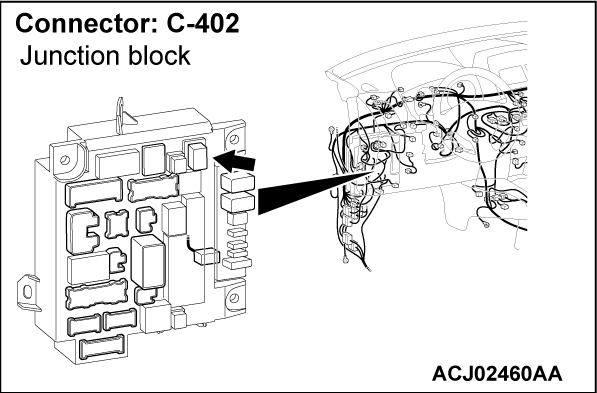
INSPECTION PROCEDURE 7: Blower motor power supply system
TECHNICAL DESCRIPTION (COMMENT)
If the blower motor is not energized, the blower relay system is suspected.
TROUBLESHOOTING HINT
- Malfunction of the blower relay
- Damaged wiring harness or connectors
- Malfunction of the ETACS-ECU
DIAGNOSIS
Required Special Tools:
- MB991223: Harness Set
- MB992006: Extra Fine Probe
STEP 1. Measure the voltage at blower relay connector C-402.
(1) Remove the relay, and measure at the ETACS-ECU side.
(2) Measure the voltage between terminal 1 and ground.
- The measured value should be approximately 12 volts (battery positive voltage).
(3) Measure the voltage between terminal 4 and ground.
- The measured value should be approximately 12 volts (battery positive voltage).
Is the check result normal?
STEP 2. Check of open circuit in blower relay power supply line between blower relay connector C-402 and fusible link (37).
| note | Prior to the wiring harness inspection, check ETACS-ECU connector and repair if necessary. |
Is the check result normal?
 Intermittent malfunction (Refer to GROUP 00 - How to Use Troubleshooting/Inspection Service Points - How to Cope with Intermittent Malfunction
  ).
). Repair the connector(s) or wiring harness.
STEP 3. Check of open circuit in blower motor line between blower motor connector C-249 and blower relay connector C-402.
| note | Prior to the wiring harness inspection, check ETACS-ECU connector and repair if necessary. |
Is the check result normal?
 Repair the connector(s) or wiring harness.
![[Previous]](../../../buttons/fprev.png)
![[Next]](../../../buttons/fnext.png)


