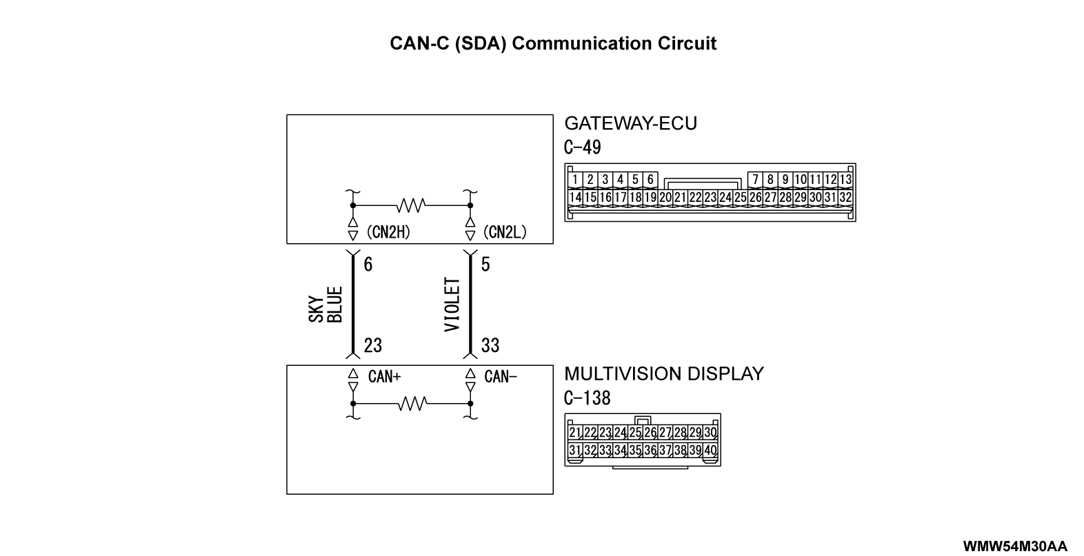
DIAGNOSTIC ITEM 17: Communication with multivision display is not possible [CAN-C (SDA)] <Vehicles with smartphone link display audio>
| caution | When servicing a CAN bus line, ground yourself by touching a metal object such as an unpainted water pipe. If you fail to do, a component connected to the CAN bus line may be broken. |
FUNCTION
The gateway-ECU receives data from the multivision display via CAN-C (SDA) line.
TROUBLE JUDGEMENT CONDITIONS
Scan tool MB991958 judges the trouble when the data from the multivision display cannot be received.
TROUBLESHOOTING HINTS
- Damaged harness wires and connectors
- Malfunction of the multivision display power supply circuit
- Malfunction of the multivision display
- Malfunction of the gateway-ECU
DIAGNOSIS
Required Special Tools:
- MB991223: Harness Set
- MB992006: Extra Fine Probe
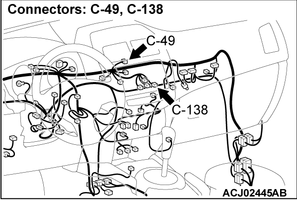
STEP 1. Connector check: gateway-ECU connector C-49 and multivision display connector C-138
| caution | The strand end of the twist wire should be within 10 cm from the connector. |
Is the check result normal?
 Repair the defective connector.
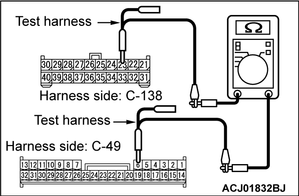
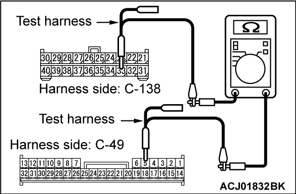
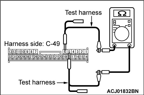
STEP 2. Continuity check between gateway-ECU connector C-49 and multivision display connector C-138
(1) Disconnect the gateway-ECU connector C-49 and multivision display connector C-138 and measure at the wiring harness side.
(2) Turn the ignition switch to the "LOCK" (OFF) position.
(3) Ensure that the negative battery terminal is disconnected.
(4) Check the continuity between gateway-ECU connector C-49 terminal No. 6 and multivision display connector C-138 terminal No. 23. <CAN_H>
OK: Continuity (2 ohms or less)
(5) Check the continuity between gateway-ECU connector C-49 terminal No. 5 and multivision display connector C-138 terminal No. 33. <CAN_L>
OK: Continuity (2 ohms or less)
Is the check result normal?
 Repair the wiring harness between the gateway-ECU connector C-49 and multivision display connector C-138.
STEP 3. Resistance measurement at gateway-ECU connector C-49 (short to ground check)
(1) Disconnect the gateway-ECU connector C-49 and multivision display connector C-138 and measure at the wiring harness side.
(2) Turn the ignition switch to the "LOCK" (OFF) position.
(3) Ensure that the negative battery terminal is disconnected.
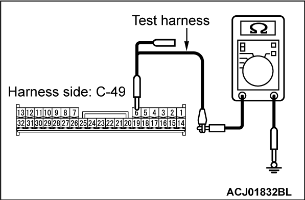
(4) Measure the resistance between gateway-ECU connector C-49 terminal No. 6 and body ground. <CAN_H>
OK: 1 kΩ or more
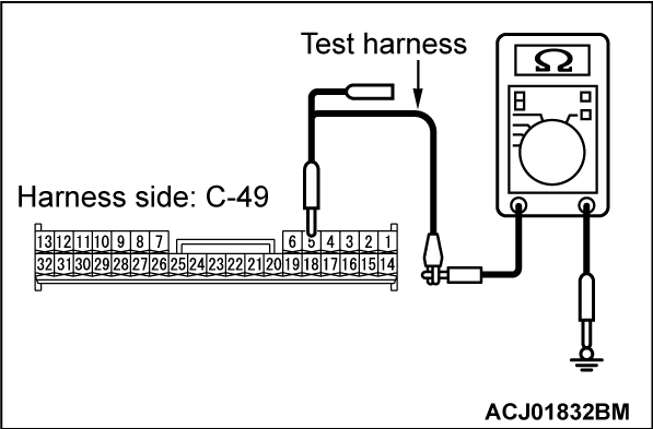
(5) Measure the resistance between gateway-ECU connector C-49 terminal No. 5 and body ground. <CAN_L>
OK: 1 kΩ or more
Is the check result normal?
 Repair the wiring harness between the gateway-ECU connector C-49 and multivision display connector C-138.
STEP 4. Voltage measurement at gateway-ECU connector C-49 (short to power supply check)
| caution |
(1) Disconnect the gateway-ECU connector C-49 and multivision display connector C-138 and measure at the wiring harness side.
(2) Connect the negative battery terminal, and turn the ignition switch to the "ON" position.
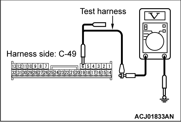
(3) Measure the voltage between gateway-ECU connector C-49 terminal No. 6 and body ground. <CAN_H>
OK: 1.0 volt or less
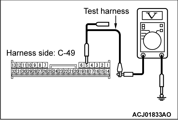
(4) Measure the voltage between gateway-ECU connector C-49 terminal No. 5 and body ground. <CAN_L>
OK: 1.0 volt or less
Is the check result normal?
 Repair the wiring harness between the gateway-ECU connector C-49 and multivision display connector C-138.
STEP 5. Resistance measurement at gateway-ECU connector C-49 (line-to-line short check)
(1) Disconnect the gateway-ECU connector C-49 and multivision display connector C-138 and measure at the wiring harness side.
(2) Turn the ignition switch to the "LOCK" (OFF) position.
(3) Ensure that the negative battery terminal is disconnected.
(4) Measure the resistance between gateway-ECU connector C-49 terminal Nos. 6 and 5.
OK: 1 kΩ or more
Is the check result normal?
 Repair the wiring harness between the gateway-ECU connector C-49 and multivision display connector C-138.
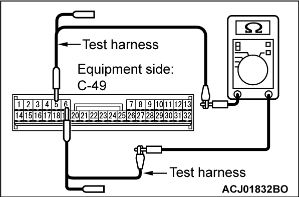
STEP 6. Resistance measurement at gateway-ECU connector C-49
| caution | A digital multimeter should be used. For details refer to  . . |
(1) Remove the C-49 gateway-ECU, and measure at the equipment side.
(2) Measure the resistance between gateway-ECU connector C-49 terminal Nos. 6 and 5.
OK: 120 ± 20 ohms
Is the check result normal?
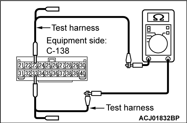
STEP 7. Resistance measurement at multivision display connector C-138
| caution | A digital multimeter should be used. For details refer to  . . |
(1) Remove the C-138 multivision display, and measure at the equipment side.
(2) Measure the resistance between multivision display connector C-138 terminal Nos. 23 and 33.
OK: 120 ± 20 ohms
Is the check result normal?
![[Previous]](../../../buttons/fprev.png)
![[Next]](../../../buttons/fnext.png)
