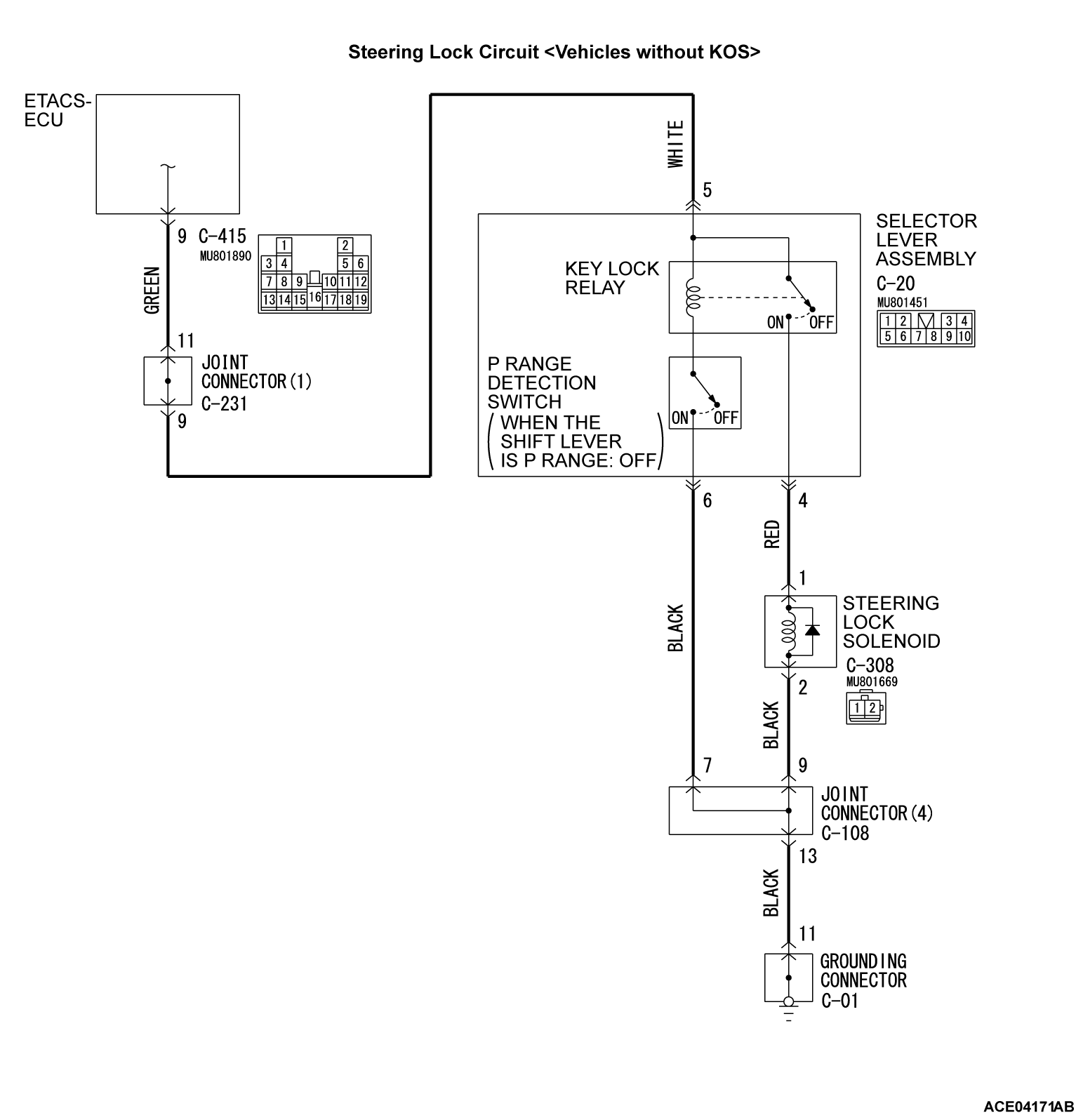
Inspection Procedure 3: Even when the selector lever is in the P position, the ignition switch cannot be turned to the LOCK (OFF) position. /When the selector lever is in other than the P position, the ignition switch can be turned to the LOCK (OFF) position.
TECHNICAL DESCRIPTION (COMMENT)
The mechanical steering lock controls the steering lock solenoid, so that the steering lock hole turns from ACC to LOCK only when the selector lever is in the P position. If the steering lock hole does not turn from ACC to LOCK even when the selector lever is in the P position, or if the steering lock hole turns from ACC to LOCK when the selector lever is in other than the P position, the steering lock solenoid, selector lever assembly, wiring harness, or connector may have a problem.
TROUBLESHOOTING HINTS
- The steering lock solenoid may be defective
- The selector lever assembly may be defective
- The wiring harness or connectors may have loose, corroded, or damaged terminals, or terminals pushed back in the connector
DIAGNOSIS
Required Special Tools:
- MB991958: Scan Tool (M.U.T.-III Sub Assembly)
- MB991824: Vehicles Communication Interface (V.C.I.)
- MB991827: M.U.T.-III USB Cable
- MB991910: M.U.T.-III Main Harness A (Vehicles with CAN communication system)
STEP 1. Using scan tool MB991958, check data list.
- Turn the ignition switch to the ACC position, and check the ETACS-ECU service data.
|
Does scan tool MB991958 display the item "ACC switch" as normal condition?
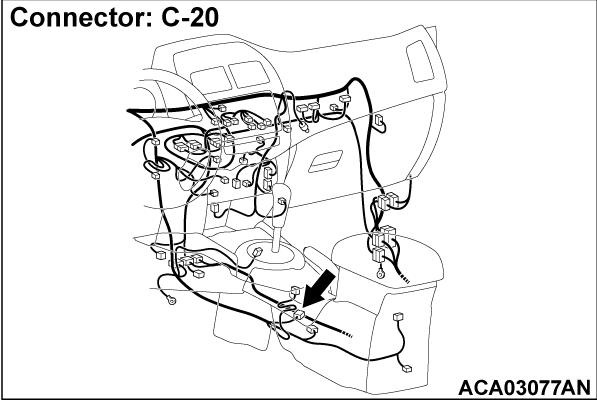
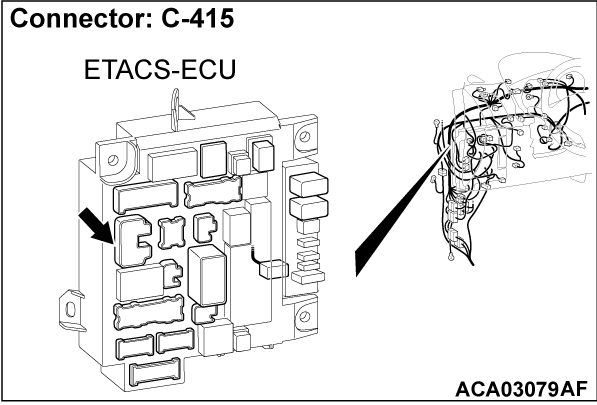
STEP 2. Check selector lever assembly connector C-20, ETACS-ECU connector C-415 for loose, corroded or damaged terminals, or terminals pushed back in the connector.
Is selector lever assembly connector C-20, ETACS-ECU connector C-415 in good condition?
 Repair the damaged parts.
STEP 3. Check the battery power supply circuit to the selector lever assembly. Measure the voltage at selector lever assembly connector C-20.
(1) Disconnect the connector, and measure at the wiring harness side.
(2) Turn the ignition switch from "ACC" position.
(3) Measure the voltage between the selector lever assembly connector C-20 terminal 5 and ground.
- The voltage should measure approximately 12 volts (battery positive voltage).
Is the measured voltage approximately 12 volts (battery positive voltage)?
STEP 4. Check the wiring harness between selector lever assembly connector C-20 (terminal 5) and ETACS-ECU connector C-415 (terminal 9).
- Check the power supply line for open or short circuit.
| note | Before the wiring harness check, check the joint connector C-231, and repair them if necessary. |
Is the check result normal?
 The trouble can be an intermittent malfunction (Refer to GROUP 00 - How to use Troubleshooting/inspection Service Points - How to Cope with Intermittent Malfunction
  ).
). Repair the wiring harness between selector lever assembly connector C-20 and ETACS-ECU connector C-415.
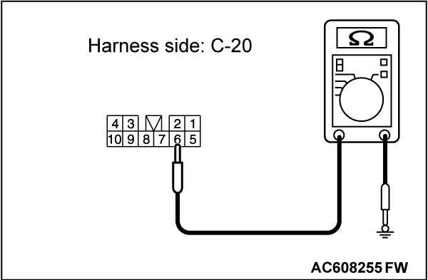
STEP 5. Check the ground circuit to the selector lever assembly. Measure the resistance at selector lever assembly connectors C-20.
(1) Disconnect the connector, and measure at the wiring harness side.
(2) Measure the resistance between the selector lever assembly connector C-20 terminal 6 and ground.
- The resistance should be 2 ohms or less.
Is the measured resistance 2 ohms or less?
STEP 6. Check the wiring harness between selector lever assembly connector C-20 (terminal 6) and ground.
- Check the ground line for open circuit.
| note | Before the wiring harness check, check the C-108 joint connector and C-01 grounding connector, and repair if necessary. |
Is the check result normal?
 The trouble can be an intermittent malfunction (Refer to GROUP 00 - How to use Troubleshooting/inspection Service Points - How to Cope with Intermittent Malfunction
  ).
). Repair the wiring harness between selector lever assembly connector C-20 and ground.
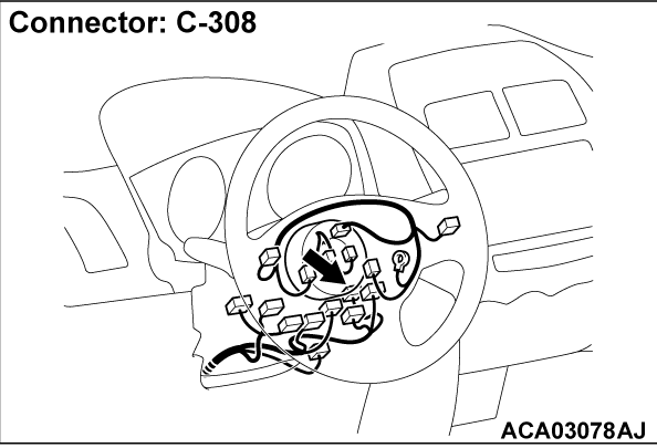
STEP 7. Check steering lock solenoid connector C-308 for loose, corroded or damaged terminals, or terminals pushed back in the connector.
STEP 8. Check of steering lock solenoid.
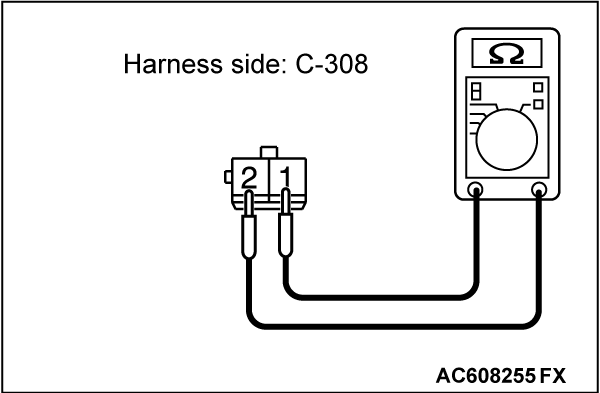
(1) Disconnect the connector, and measure the resistance at the equipment side.
(2) Measure the resistance between the steering lock solenoid connector C-308 terminal 1 and 2.
- The resistance should be 2 ohms or less.
Is the steering lock solenoid in good condition?
 Replace the steering lock solenoid.
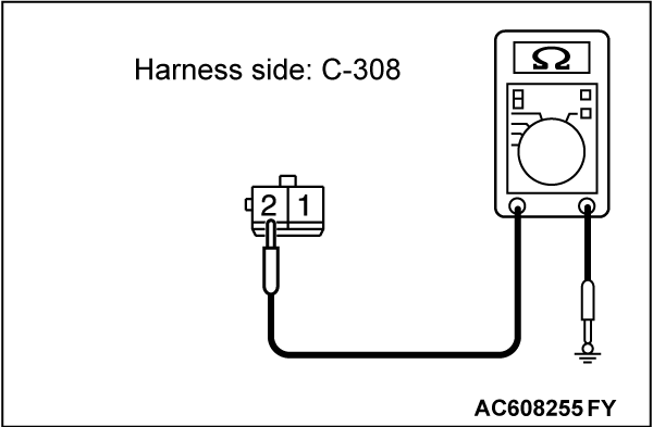
STEP 9. Check the ground circuit to the steering lock solenoid. Measure the resistance at steering lock solenoid connector C-308.
(1) Disconnect the connector, and measure at the wiring harness side.
(2) Measure the resistance between the steering lock solenoid connector C-308 terminal 2 and ground.
- The resistance should be 2 ohms or less.
Is the measured resistance 2 ohms or less?
STEP 10. Check the wiring harness between steering lock solenoid connector C-308 (terminal 2) and ground.
| note | Before the wiring harness check, check the joint connector C-108 and grounding connector C-01, and repair them if necessary. |
- Check the ground line for open circuit.
Is the check result normal?
 The trouble can be an intermittent malfunction (Refer to GROUP 00 - How to use Troubleshooting/inspection Service Points - How to Cope with Intermittent Malfunction
  ).
). Repair the wiring harness between steering lock solenoid connector C-308 and ground.
STEP 11. Check the wiring harness between selector lever assembly connector C-20 (terminal 4) and steering lock solenoid connector C-308 (terminal 1).
- Check the signal line for open or short circuit.
Is the check result normal?
 Repair the wiring harness.
STEP 12. Retest the system
When the ignition switch can be turned to the LOCK (OFF) position when the selector lever is in the P position? Or, When the ignition switch cannot be turned to the LOCK (OFF) position when the selector lever is in other than the P position?
 The trouble can be an intermittent malfunction (Refer to GROUP 00, How to use Troubleshooting/inspection Service Points - How to Cope with Intermittent Malfunction
  ).
). Replace the selector lever assembly.
![[Previous]](../../../buttons/fprev.png)
![[Next]](../../../buttons/fnext.png)
