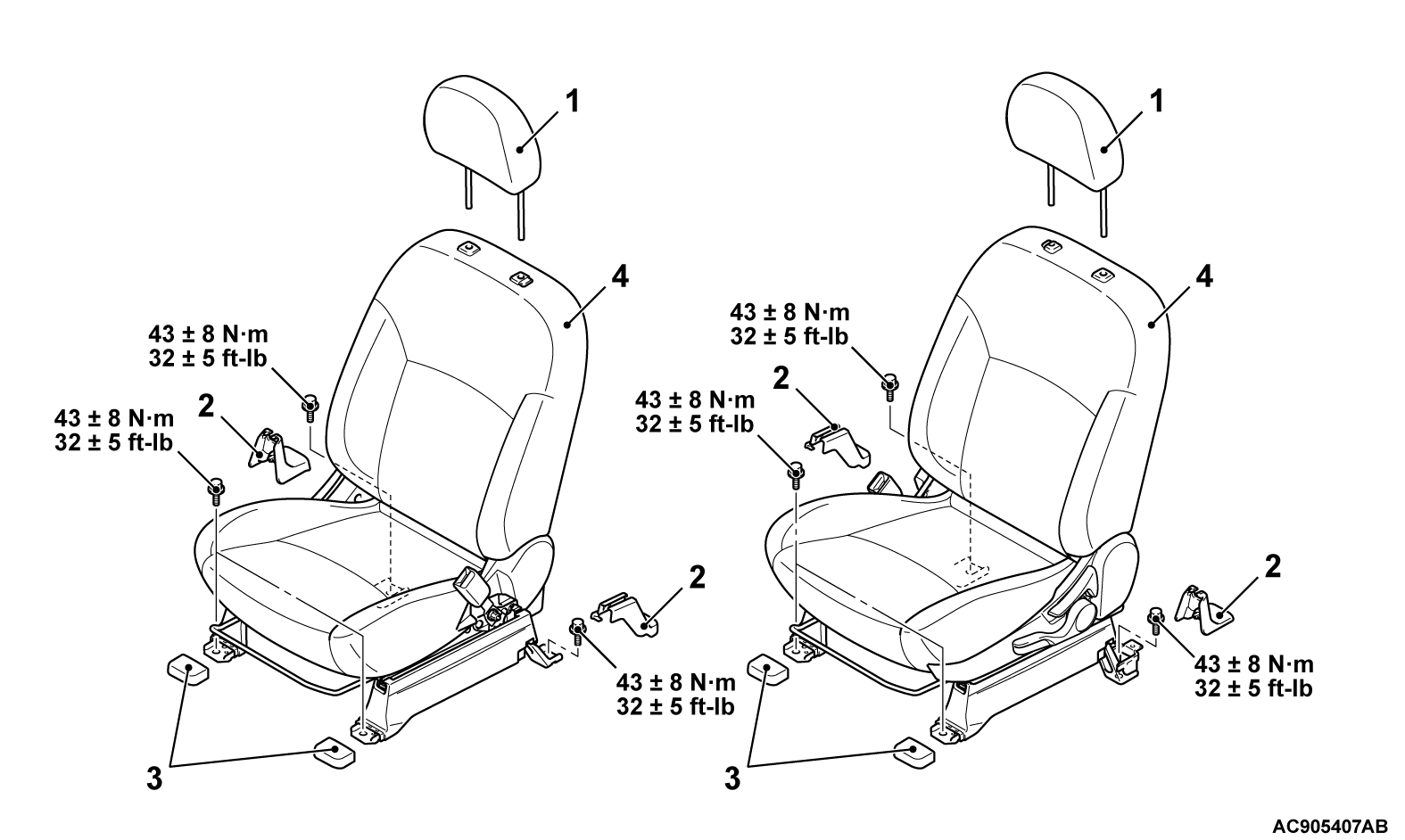
REMOVAL AND INSTALLATION
| caution | Before removing the front seat assembly, refer to GROUP 52B, Service Precautions  and Side Airbag Module (s) and Side Airbag Module (s)  . . |
REMOVAL SERVICE POINT
<<A>> WIRING HARNESS CONNECTORS DISCONNECTION
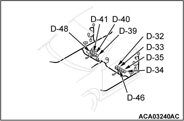
Disconnect the following wiring harness connectors:
| Connector number | Connector name |
| D-32 (2 - yellow) | Side-airbag module (squib) (LH) |
| D-33 (4 - black) | Seat belt switch (Driver's side) |
| D-34 (2) | Power seat assembly |
| D-35 (4 - black) | Heated seat (LH) |
| D-46 (2 - gray) | Seat slide sensor |
| D-39 (2 - yellow) | Side-airbag module (squib) (RH) |
| D-40 (2 - black) | Seat belt switch (Passenger's side) |
| D-41 (4 - black) | Heated seat (RH) |
| D-48 (6) | Front seat assembly (RH) |
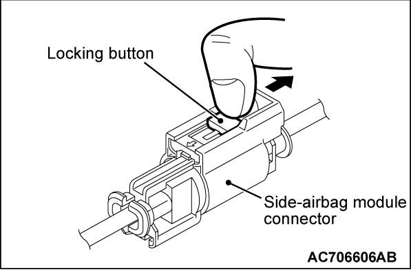
| note | When disconnecting the side air bag module connectors of D-32 and D-39, unlock the connector by sliding the locking button to the direction of the arrow as shown in the figure, and then disconnect the connector. |
INSTALLATION SERVICE POINT
![[Previous]](../../../buttons/fprev.png)
![[Next]](../../../buttons/fnext.png)


