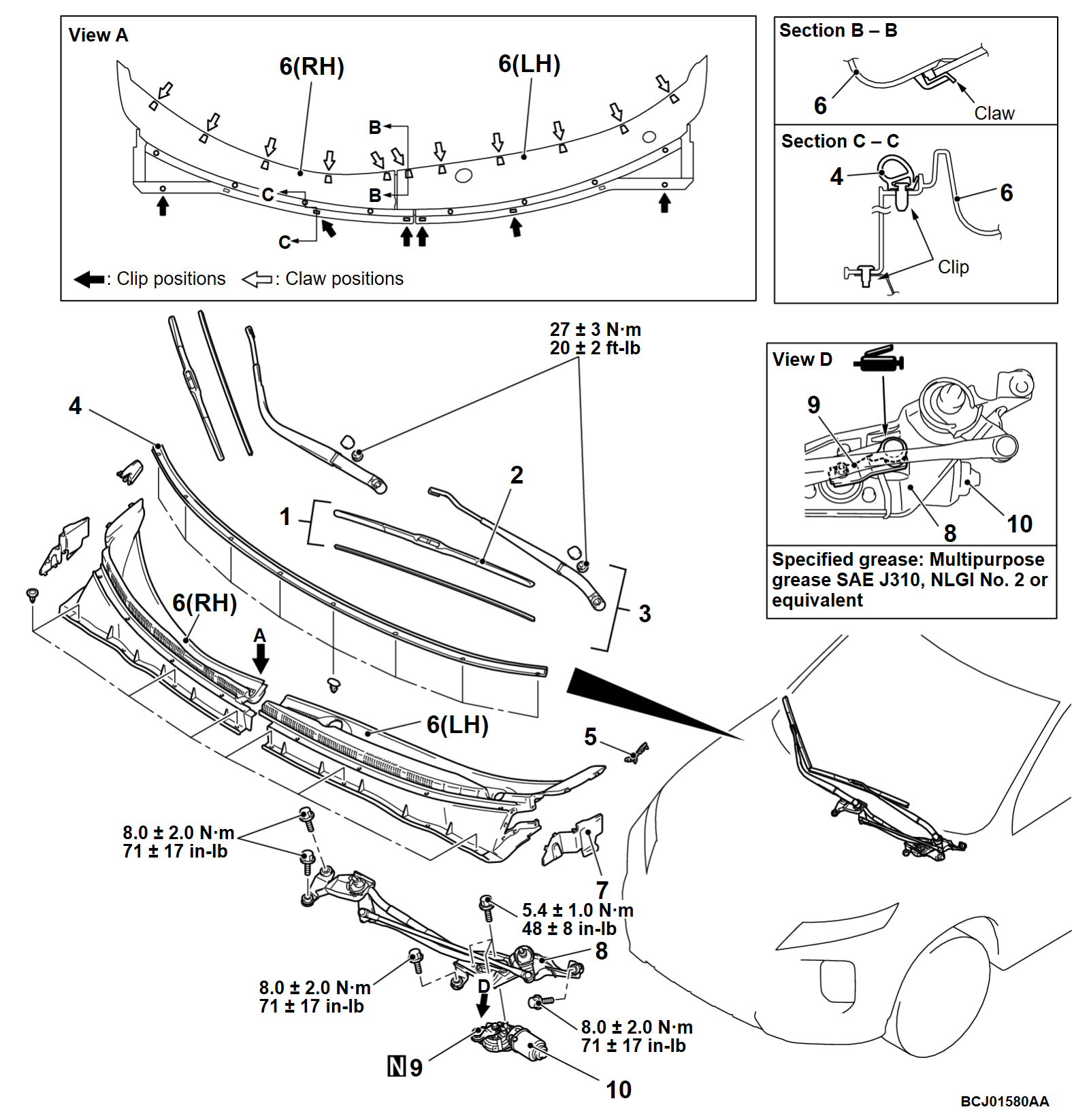
REMOVAL AND INSTALLATION
| note | For removal and installation of the wiper and washer switch, refer to GROUP 54A, Column switch  . . |
REMOVAL SERVICE POINT
INSTALLATION SERVICE POINTS
>>A<< WINDSHIELD WIPER MOTOR INSTALLATION
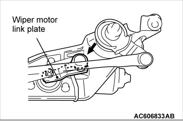
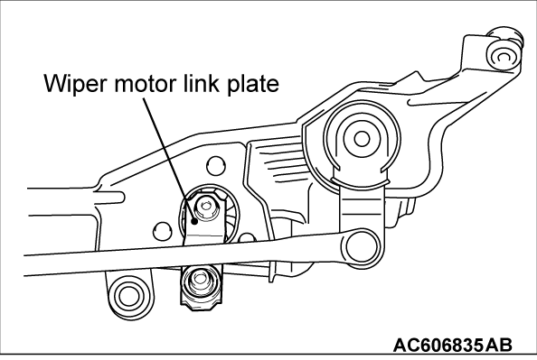
1. Position the wiper motor link plate as shown, and assemble it to the wiper link assembly.
| note |
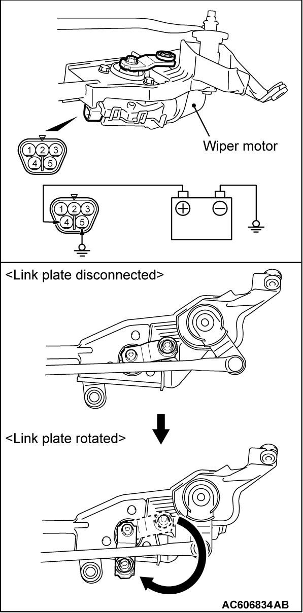
2. Connect the assembled wiper motor to a battery, and set it to the automatic stop position (Refer to Stop position check,  ).
).
 ).
).3. Apply grease to the inside of link rod joint (as required) and connect the link rod to wiper motor link plate.
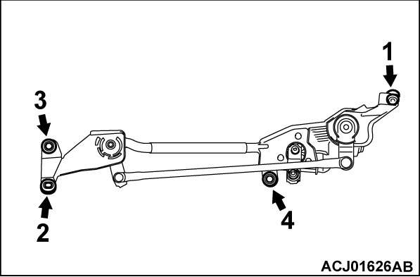
4. Tighten the bolts to the specified torque in the order shown.
Tightening torque: 8.0 ± 2.0 N·m (71 ± 17 in-lb)
>>B<< WIPER ARM AND BLADE ASSEMBLY INSTALLATION
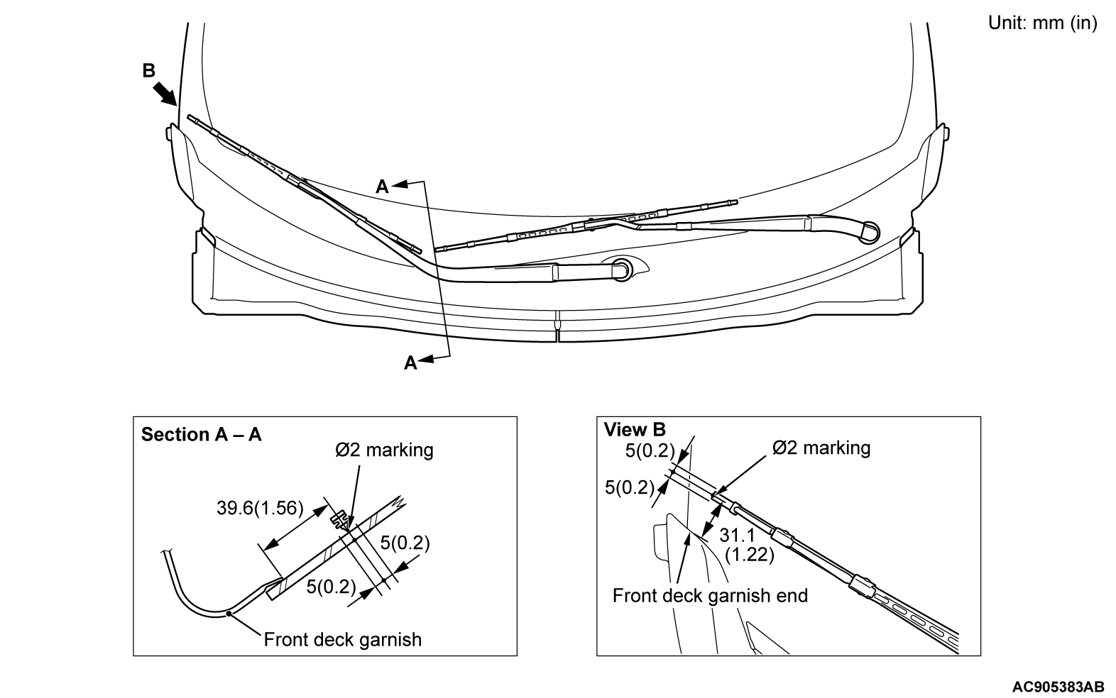
Install the wiper arm and blade assembly at the specified positions.
(A): Φ 2 marking ± 5 mm(0.2 in)
![[Previous]](../../../buttons/fprev.png)
![[Next]](../../../buttons/fnext.png)
