DISASSEMBLY AND ASSEMBLY
Required Special Tools:
- MB992209: Bellows Band Clipping Tool
- MB992249: Variable Spanner
DISASSEMBLY SERVICE POINT
<<A>> TIE-ROD REMOVAL
1.
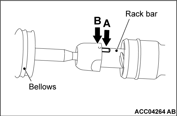
Fold the left bellows back, and then use a spanner to counterhold the flats (A) on the rack end.
| caution | Be careful not to damage the rack bar and the teeth surface. |
2. Apply the special tool "variable spanner" MB992249 to the B portion as shown to remove the tie rod.
| note | There are not flats on the right rack bar. Therefore, counterhold the left rack end even when you remove the right tie rod. |
ASSEMBLY SERVICE POINTS
>>A<< TIE-ROD INSTALLATION
1.
Fold the left bellows back, and then use a spanner to counterhold the flats (A) on the rack end.
| caution | Be careful not to damage the rack bar and the teeth surface. |
2. Apply the special tool "variable spanner" MB992249 to the B portion as shown to tighten the tie rod to the specified torque.
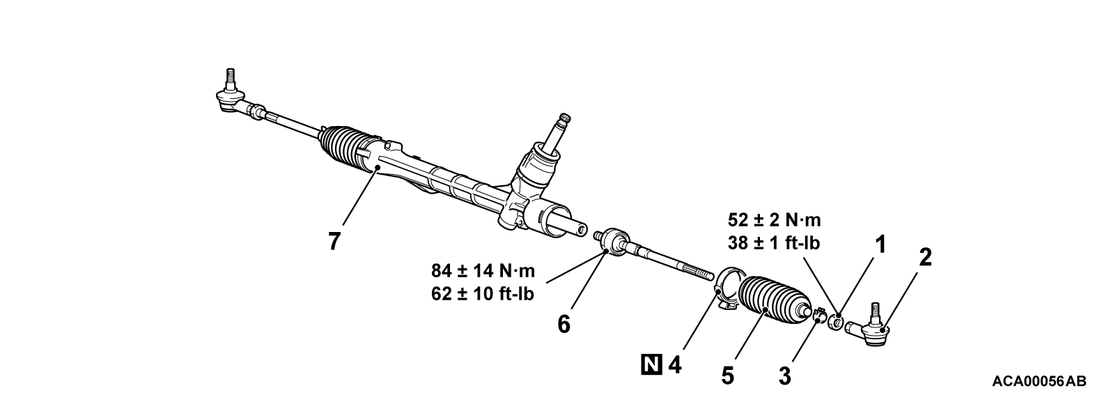
Tightening torque: 84 ± 14 N·m (62 ± 10 ft-lb)
| note | There are not flats on the right rack bar. Therefore, counterhold the left rack end even when you install the right tie rod. |
>>B<< BAND INSTALLATION
1.
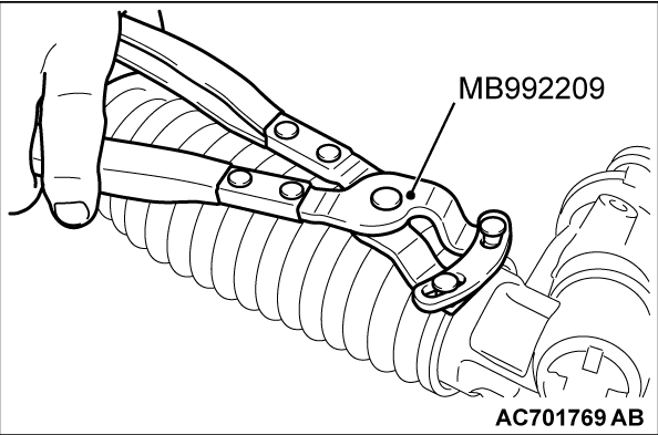
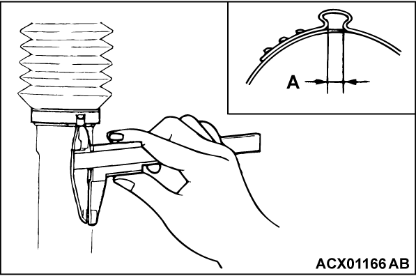
Use special tool MB992209 to crimp the bellows band.
| caution |
|
2. Check that crimped width (A) is within the standard value.
Standard value (A): 2.4 - 2.8 mm (0.10 - 0.11 inch)
![[Previous]](../../../buttons/fprev.png)
![[Next]](../../../buttons/fnext.png)
