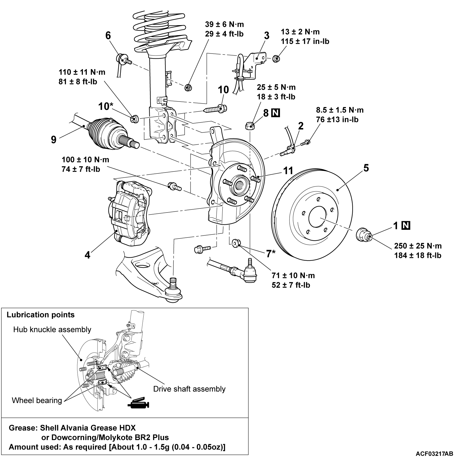
REMOVAL AND INSTALLATION
| caution |
|
Post-installation operation Using your fingers, press the Ball Joint Dust Cover to check for a crack or damage. |
Required Special Tools:
- MB990242: Puller Shaft
- MB990244: Puller Bar
- MB990767: Front Hub and Flange Yoke Holder
- MB991354: Puller Body
- MB991897 or MB992011: Ball Joint Remover
- MB992700: Lock Nut Chisel
REMOVAL SERVICE POINTS
<<A>> DRIVESHAFT NUT REMOVAL
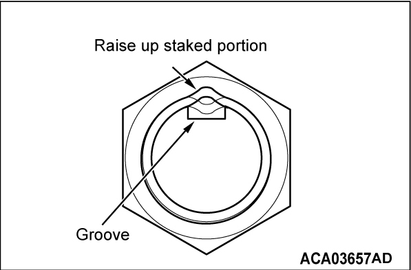
1. The staked portion of the driveshaft nut must face upwards.
2.
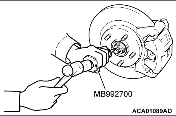
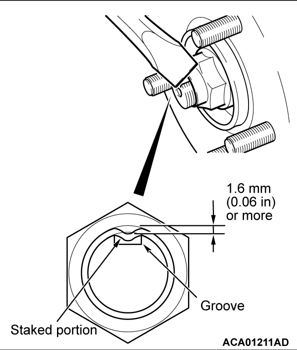
Set the special tool MB992700 in the groove of the driveshaft with its "UPPER" mark facing upwards. Then strike the staked portion of the driveshaft nut with the chisel and a hammer to raise up.
| caution |
|
3.
Raise up the staked portion of the driveshaft nut until it does not interfere with the shaft thread.
| caution | Be careful not to damage the thread of the driveshaft. |
4.
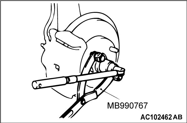
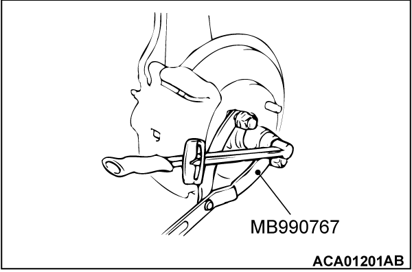
Use special tool MB990767 to counter the hub as shown in the figure to remove the driveshaft nut.
| caution |
|
<<B>> BRAKE CALIPER ASSEMBLY REMOVAL
1. Remove the brake caliper assembly with brake hose.
2. Secure the removed caliper assembly with a wire or other similar material at a position where it will not interfere with the removal and installation of the hub knuckle assembly.
<<C>> STABILIZER LINK DISCONNECTION
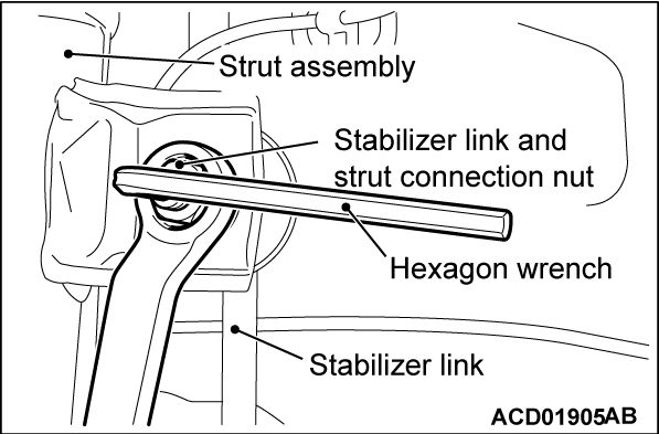
Use a wrench to counterhold the stabilizer link as shown. Then use a hexagon wrench to remove the nut securing the stabilizer link to the strut.
<<D>> SELF-LOCKING NUT (TIE-ROD END CONNECTION) REMOVAL
1.
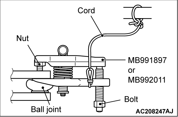
Install special tool MB991897 or MB992011 as shown in the figure.
| caution |
|
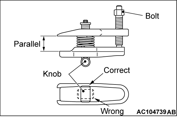
2. Turn the bolt and knob to make the special tool jaws parallel, then hand-tighten the bolt. After tightening, check that the jaws are still parallel.
| note | To adjust the special tool jaws to be parallel, set the orientation of the knob as shown in the figure. |
3. Unscrew the bolt to disconnect the ball joint.
<<E>> DRIVESHAFT AND HUB KNUCKLE DISCONNECTION
| caution |
|
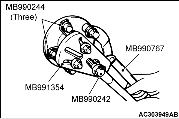
If the driveshaft is seized, use special tools MB990242 and MB990244, MB991354 and MB990767 to push the driveshaft out from the hub.
INSTALLATION SERVICE POINTS
>>A<< STABILIZER LINK CONNECTION
Use a hexagon wrench to counterhold the stabilizer link as shown. Then use a wrench to install the nut securing the stabilizer link to the strut.
>>B<< DRIVESHAFT NUT INSTALLATION
| caution |
|
1. Check the hub seated surface for damage or corrosion.Whenever solvent is used for removing the corrosion, the surface should be degreased.
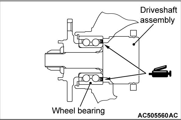
2. Apply the grease as shown and then insert the drive shaft assembly into the front hub.
Specified grease: Shell Alvania Grease HDX or Dowcorning/Molykote BR2 Plus
Amount to use: As required [About 1.0 - 1.5 g (0.04 - 0.05 oz)]
3. Check that the new driveshaft nut can be turned smoothly by hand. Then tighten it until it is seated.
4. Using special tool MB990767, tighten the driveshaft nut.
Tightening torque: 250 ± 25 N·m (184 ± 18 ft-lb)
5. After tightening to the specified torque, check that the nut is seated securely.
6. Use the chisel and a hammer to stake the nut until the center in the staked portion reaches the shown dimension.
7. Finally, check that the nut is not cracked at its staked portion.
![[Previous]](../../../buttons/fprev.png)
![[Next]](../../../buttons/fnext.png)
