[Previous][Next]
REMOVAL AND INSTALLATION
caution
  • Before replacing the valve body assembly, you should make a note of the serial No. which is stamped on the new valve body assembly (Refer to ).
  • When the valve body assembly is replaced, carry out the following operations.
    • Initialization Procedure for CVT Learned Value (Refer to .)
    • Learning Procedure (Refer to .)
 
 
Pre-removal operation
  • Engine Room Under Cover Front A, B and Engine Room Side Cover (LH) Removal. (Refer to GROUP 51 - Under Cover )
  • CVT Assembly Connector Disconnection.
  • CVT Fluid Draining (Refer to ).
Post-installation operation
  • Engine Room Under Cover Front A, B and Engine Room Side Cover (LH) Installation. (Refer to GROUP 51 - Under Cover )
  • CVT Assembly Connector Connection.
  • CVT Fluid Refilling (Refer to ).
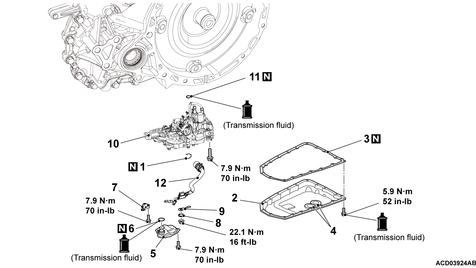
Removal steps
<<A>>1.Snap ring
>>E<<2.Oil pan
>>D<<3.Oil pan gasket
4.Magnet
>>C<<5.Oil strainer
6.O-ring
7.Bracket
8.Spring washer
9.Manual lever
<<B>>>>B<<10.Valve body assembly
>>A<<11.Lip seal
12.Valve body harness


REMOVAL SERVICE POINTS
 
 
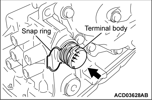
<<A>> SNAP RING REMOVAL
cautionBe careful not to cause damage to the terminal body.
Remove the snap ring from the terminal body, and press the terminal body into the transaxle case.


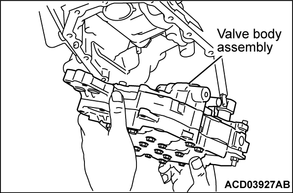
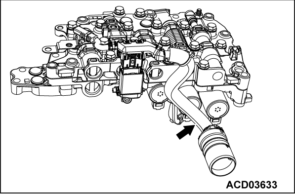
<<B>> VALVE BODY ASSEMBLY REMOVAL
Tilt the valve body assembly, and after removing from the manual shaft side, remove the terminal body from the transaxle case.


INSTALLATION SERVICE POINTS
 
 
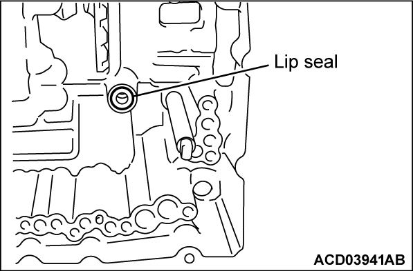
>>A<< LIP SEAL INSTALLATION
caution
  • Do not re-use the lip seal.
  • Apply transmission fluid or vaseline when installing the lip seal.


>>B<< VALVE BODY ASSEMBLY INSTALLATION
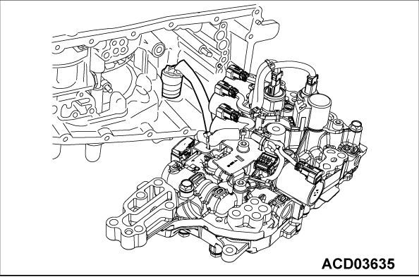
Install the valve body assembly on the transaxle case as follows.
1. Install the valve body harness on the valve body assembly.
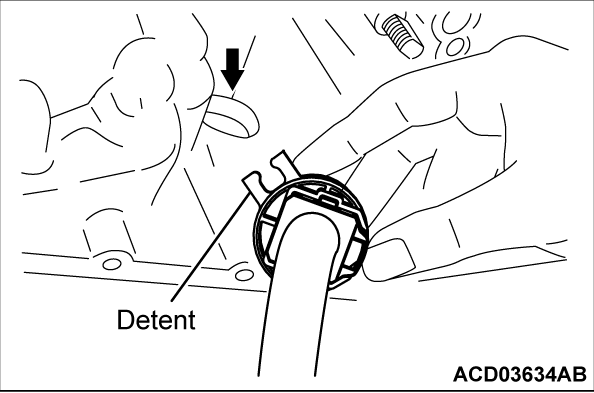
2.
caution
  • Push in the valve body harness until the detent contacts the transaxle case.
  • Be careful not to cause damage to the terminal body.
Install the terminal body on the transaxle case, while aligning the detent of terminal body with the transaxle case as shown in the diagram.
3. Slide the valve body assembly from the left side, and install it on the transaxle case.
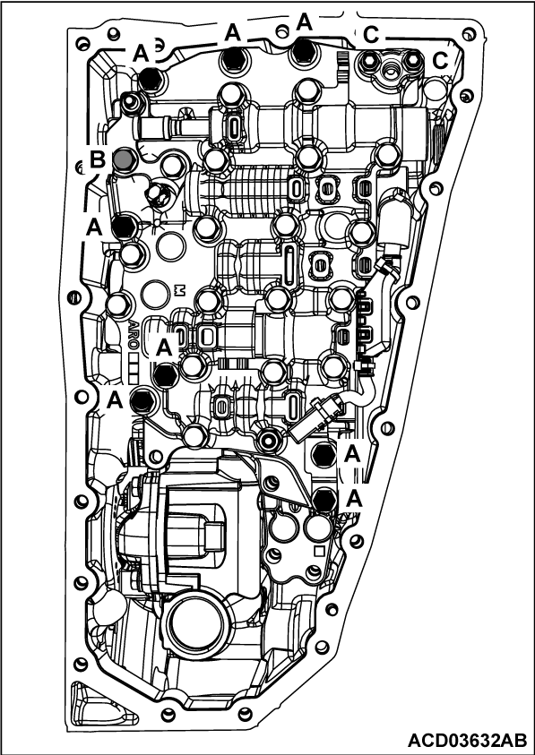
4. Install the fastening bolts of valve body assembly, and tighten to the specified torque of 7.9 N·m (70 in-lb).
 
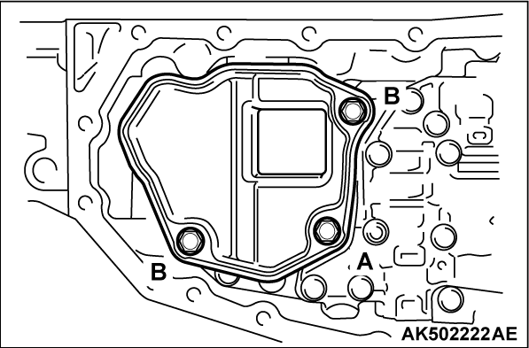
Bolt symbolABC
Shank length mm (inch)54 (2.1)44 (1.7)54 (2.1)
Quantity812


>>C<< OIL STRAINER INSTALLATION
Install the oil strainer, and tighten the fastening bolts to the specified torque of 7.9 N·m (70 in-lb).
 
Bolt symbolAB
Shank length mm (inch)44 (1.7)12 (0.5)
Quantity12


>>D<< OIL PAN GASKET INSTALLATION
caution
  • Do not re-use the oil pan gasket.
  • Remove any moisture, oil, and used gasket from the mounting surface of oil pan gasket.
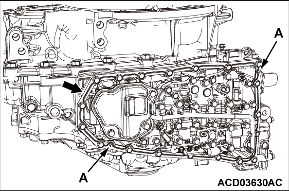
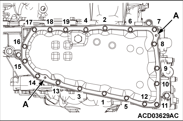
  • When installing the oil pan gasket, align the dowel pins of transaxle case with dowel pin holes A of the oil pan gasket.


>>E<< OIL PAN INSTALLATION
cautionWhen installing the oil pan, align the dowel pins of transaxle case with dowel pin holes A of the oil pan.
Tighten each oil pan mounting bolt to the specified torque of 5.9 N·m (52 in-lb) in the order of number shown.