DTC P0705: Malfunction of Transmission Range Switch
DIAGNOSTIC FUNCTION
TCM monitors the signal from the transmission range switch, and determines if the abnormal input is present or not.
DESCRIPTIONS OF MONITOR METHODS
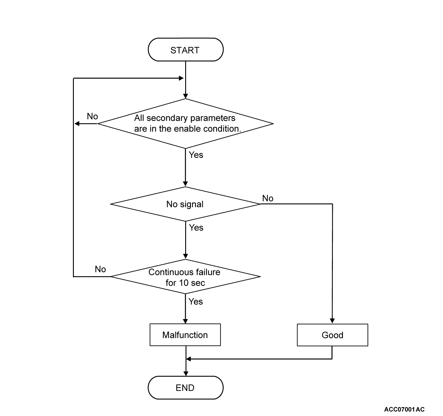
- TCM does not detects the transmission range switch input signal when the vehicle speed is 3 km/h (2 mph) or more for 10 seconds continuously.
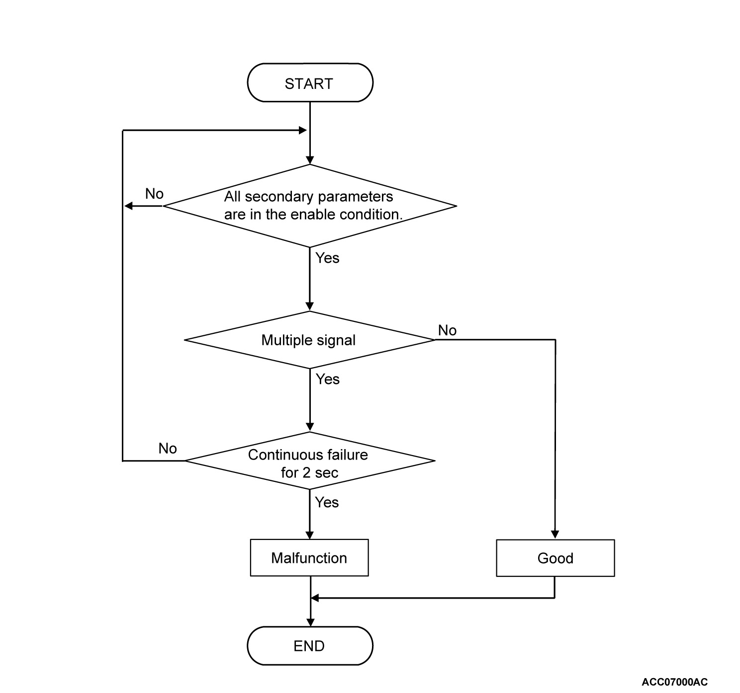
- TCM detects the multiple inputs from the transmission range switch for 2 seconds.
MONITOR EXECUTION
- Vehicle speed (no-transmission range switch signal input): 3 km/h (2 mph) or more for 10 seconds continuously
- Vehicle speed (transmission range switch signal multiple input): No conditions
- Voltage of battery: 10 volts or more.
MONITOR EXECUTION CONDITIONS (OTHER MONITOR AND SENSOR)
Other Monitor (There is no temporary DTC stored in memory for the item monitored below)
- P0711, P0712, P0713: Malfunction of the transmission fluid temperature sensor
- P0715: Malfunction of primary pulley speed sensor
- P0720: Malfunction of secondary pulley speed sensor
- P0730: Incorrect gear ratio
- P0966, P0967: Malfunction of secondary pressure solenoid valve
- P0970, P0971: Malfunction of primary pressure solenoid valve
- P2720, P2721: Malfunction of select pressure solenoid valve
- P2765: Malfunction of turbine speed sensor
Sensor (The sensor below is determined to be normal)
- Transmission fluid temperature sensor
- Primary pulley speed sensor
- Secondary pulley speed sensor
- Turbine speed sensor
DTC SET CONDITIONS
Check Conditions
- Vehicle speed over 3 km/h (2 mph): 10 seconds or more.
- Voltage of battery: 10 volts or more.
Judgment Criteria
- Transmission range switch: multiple signal. (2 seconds)
- Transmission range switch: no signal. (10 seconds)
OBD-II DRIVE CYCLE PATTERN
Transmission range: D (Drive the vehicle for 10 seconds or more while the accelerator opening angle is 20% or more)
PROBABLE CAUSES
- Malfunction of the transmission range switch
- Improper adjustment of transaxle control cable
- Damaged wiring harness and connectors
- Malfunction of TCM
DIAGNOSIS
STEP 1. Voltage measurement at transmission range switch connector (terminal No. 3)
(1) Disconnect the transmission range switch connector, and measure at the wiring harness side.
(2) Turn the ignition switch to the "ON" position.
(3) Measure the voltage between the transmission range switch connector (terminal No. 3) and body ground.
OK: 10 V or more
Is the check result normal?
 Repair the connector(s) or the wiring harness (power supply line between the transmission range switch connector terminal No. 3 and the ETACS-ECU connector).
STEP 2. Check for open circuit or short to ground in INHP, INHR, INHN, INHD and INHL line between the transmission range switch connector and the TCM connector
STEP 3. Transmission range switch and control cable adjustment
STEP 5. Voltage measurement at TCM connector (INHP, INHR, INHN, INHD and INHL terminal)
(1) Connect the transmission range switch connector.
(2) Disconnect the TCM connector, and measure at the wiring harness side.
(3) Turn the ignition switch to the "ON" position.
(4) Measure the voltage at each terminal when the selector lever is moved to each range.
- At P range: Between the TCM connector (INHP terminal) and body ground
- At R range: Between the TCM connector (INHR terminal) and body ground
- At N range: Between the TCM connector (INHN terminal) and body ground
- At D range: Between the TCM connector (INHD terminal) and body ground
- At L range: Between the TCM connector (INHL terminal) and body ground
OK: 10 V or more
Is the check result normal?
 Repair the connector(s) or the wiring harness.
![[Previous]](../../../buttons/fprev.png)
![[Next]](../../../buttons/fnext.png)


