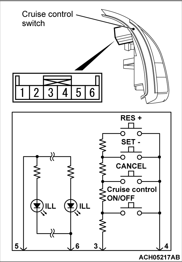
CRUISE CONTROL SYSTEM COMPONENT CHECK
CRUISE CONTROL SWITCH CHECK
2. Measure the resistance between terminal number 3 and terminal number 4 when each of the "CRUISE ON/OFF", "CANCEL", "SET-" and "RES+" switches is pressed. If the values measured at the time each switch is pressed correspond to those in the table below, the resistance values are correct.
|
3. Check that illumination of the cruise control switch turns on when the battery positive terminal is connected to cruise control switch connector terminal No.5, and the battery negative terminal is connected to cruise control switch connector terminal No.6.
![[Previous]](../../../buttons/fprev.png)
![[Next]](../../../buttons/fnext.png)

