DTC P0620: Generator Control Circuit
CIRCUIT OPERATION
- When the ignition switch is turned ON, the current should be supplied from the ECM (terminal No. 62) to the generator (terminal No. 3). When the engine starts under those conditions, the generator should generate currents.The generated voltage is applied to the ECM (terminal No. 62) from the generator (terminal No. 3). This allows the ECM to detect that the electrical generation begins.
- The ECM (terminal No. 60) controls the generator output voltage by turning the power transistor in the unit ON/OFF according to the electrical load.
TECHNICAL DESCRIPTION
The ECM Compares the battery voltage with the voltage generated from the generator to check whether the electrical generation is normal.
DESCRIPTION OF MONITOR METHOD
The difference exceeds the specified value between the target generation voltage and the battery backup voltage.
DTC SET CONDITION
Check Conditions
- Ignition switch is "ON" position.
- The engine speed is 600 r/min or more.
- The battery backup voltage is 13.5 volts or more.
- The G-terminal duty ratio is 80 percent or less and the malfunction of DTC P0622 is not detected.
Judgment Criterion
- For 30 seconds, the final target generation voltage subtracted from the battery backup voltage equals 0.8 volt or more.
or
- For 30 seconds, the battery backup voltage subtracted from the final target generation voltage equals 1.3 volts or more.
PROBABLE CAUSES
- Battery failed.
- Drive belt failed.
- Open/shorted generator G-terminal circuit, or connector damage.
- Open/shorted generator L-terminal circuit, or connector damage.
- Battery backup circuit harness damage or connector damage.
- Generator failed.
- ECM failed.
DIAGNOSIS
Required Special Tools:
- MB991958: Scan Tool (M.U.T.-III Sub Assembly)
- MB991824: V.C.I.
- MB991827: USB Cable
- MB991910: Main Harness A
- MB992110: Power Plant ECU Check Harness
STEP 1. Checking engine start conditions
- Check whether the user uses the booster cable to start the engine.
| note | This diagnostic trouble code (DTC) can be output due to the battery voltage drop. |
Have you ever used the booster cable to start the engine?
 Delete the DTC and check end.
STEP 2. Check battery itself
Is the check result normal?
STEP 3. Check drive belt tension
Is the check result normal?
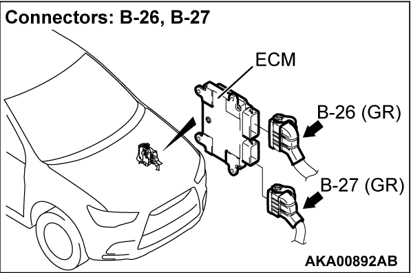
STEP 4. Check harness connector B-26 at ECM for damage.
Is the harness connector in good condition?
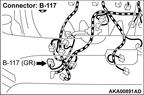
STEP 5. Check harness connector B-117 at generator for damage.
Is the harness connector in good condition?
STEP 6. Check for open circuit, short circuit to ground and damage between generator connector B-117 (terminal No. 1) and ECM connector B-26 (terminal No. 60).
STEP 7. Check for open circuit, short circuit to ground and damage between generator connector B-117 (terminal No. 3) and ECM connector B-26 (terminal No. 62).
STEP 8. Check harness connector B-27 at ECM for damage.
Is the harness connector in good condition?
STEP 9. Check for harness damage between battery and ECM connector B-27 (terminal No. 104).
STEP 10. Using scan tool MB991958, read the diagnostic trouble code (DTC).
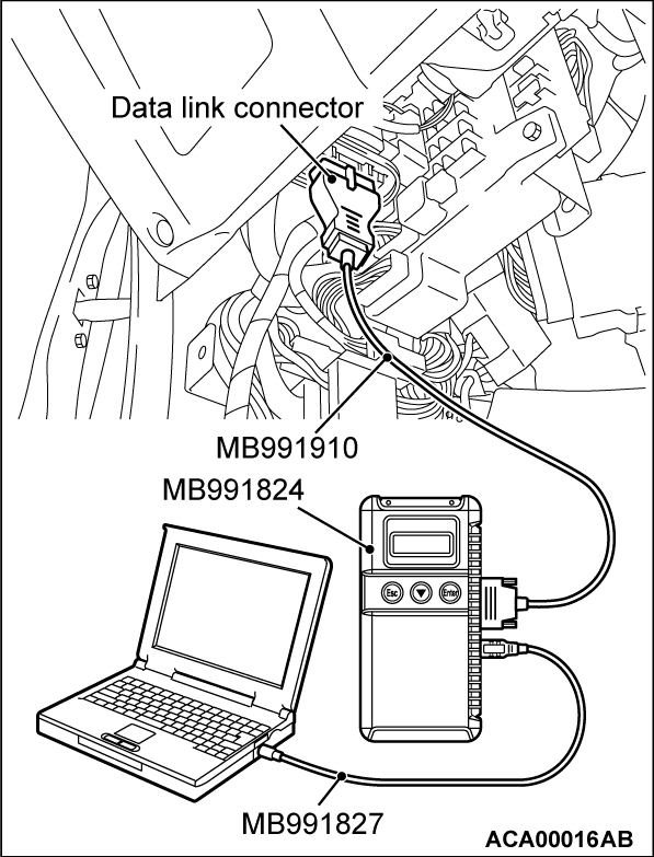
(1) Connect scan tool MB991958 to the data link connector.
(2) Start the engine and run at idle.
(3) After the DTC has been deleted, read the DTC again.
(4) Turn the ignition switch to the "LOCK" (OFF) position.
Is DTC P0620 set?
STEP 11. Replace the drive belt.
(1) Replace the drive belt.
(2) Connect scan tool MB991958 to the data link connector.
(3) Start the engine and run at idle.
(4) After the DTC has been deleted, read the DTC again.
(5) Turn the ignition switch to the "LOCK" (OFF) position.
Is DTC P0620 set?
 The inspection is complete.
STEP 12. Replace the generator.
(1) Replace the generator.
(2) Connect scan tool MB991958 to the data link connector.
(3) Start the engine and run at idle.
(4) After the DTC has been deleted, read the DTC again.
(5) Turn the ignition switch to the "LOCK" (OFF) position.
Is DTC P0620 set?
 The inspection is complete.
STEP 13. Using scan tool MB991958, read the diagnostic trouble code (DTC).
(1) Connect scan tool MB991958 to the data link connector.
(2) Start the engine and run at idle.
(3) After the DTC has been deleted, read the DTC again.
(4) Turn the ignition switch to the "LOCK" (OFF) position.
Is DTC P0620 set?
 Retry the troubleshooting.
 The inspection is complete.
![[Previous]](../../../buttons/fprev.png)
![[Next]](../../../buttons/fnext.png)


