DTC P0606: Engine Control Module Main Processor Malfunction
ENGINE CONTROL MODULE MAIN PROCESSOR MALFUNCTION CIRCUIT
CIRCUIT OPERATION
TECHNICAL DESCRIPTION
- Throttle actuator control processor checks the ECM for abnormal conditions.
DESCRIPTIONS OF MONITOR METHODS
- No watch dog pulse is detected.
MONITOR EXECUTION
- Continuous
MONITOR EXECUTION CONDITIONS (Other monitor and Sensor)
Other Monitor (There is no temporary DTC stored in memory for the item monitored below)
- Not applicable
Sensor (The sensor below is determined to be normal)
- Not applicable
DTC SET CONDITIONS
Check Condition
- Ignition switch is "ON" position.
Judgment Criterion
- No surveillance pulse signals is inputted for 0.5 second.
FAIL-SAFE AND BACKUP FUNCTION
- Throttle opening degree position is in default position.
OBD-II DRIVE CYCLE PATTERN
- None.
TROUBLESHOOTING HINTS (The most likely causes for this code to be set are:)
- MFI relay failed.
- Shorted MFI relay circuit or connector damage.
- Open or shorted ignition switch-IG circuit, harness damage or connector damage.
- ECM failed.
DIAGNOSIS
Required Special Tool:
- MB991958: Scan Tool (M.U.T.-III Sub Assembly)
- MB991824: V.C.I.
- MB991827: USB Cable
- MB991910: Main Harness A
STEP 1. Check the battery.
STEP 2. Check harness connector B-27 at ECM for damage.
Is the harness connector in good condition?
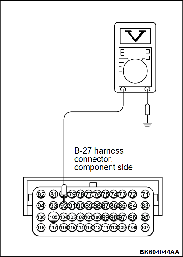
STEP 3. Measure the ignition switch-IG signal voltage at ECM harness side connector B-27.
(1) Disconnect the connector B-27 and measure at the harness side.
(2) Turn the ignition switch to the "ON" position.
(3) Measure the voltage between terminal No. 92 and ground.
- Voltage should be battery positive voltage.
(4) Turn the ignition switch to the "LOCK" (OFF) position.
Is battery positive voltage (approximately 12 volts) present?
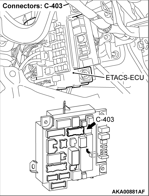
STEP 4. Check harness connector C-403 at ETACS-ECU for damage.
Is the harness connector in good condition?
STEP 5. Check harness connector C-403 at ETACS-ECU for damage.
Is the harness connector in good condition?
STEP 6. Check for harness damage between ETACS-ECU connector C-403 (terminal No. 10) and ECM connector B-27 (terminal No. 92).
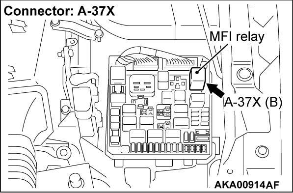
STEP 7. Check harness connector A-37X at MFI relay for damage.
Is the harness connector in good condition?
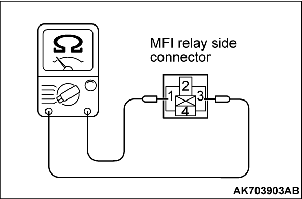
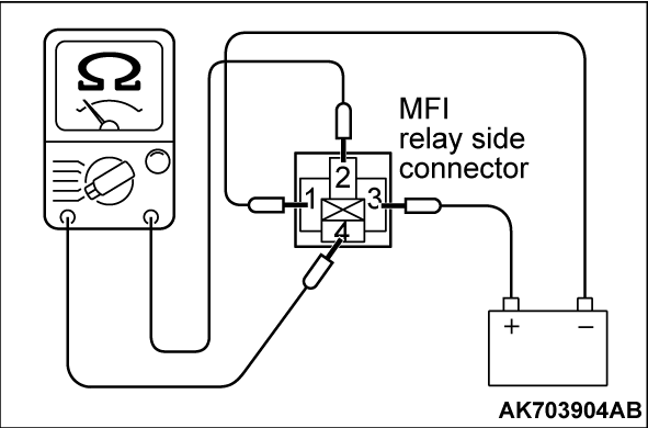
STEP 8. Check the MFI relay.
(1) Remove the MFI relay.
(2) Check for continuity between the MFI relay terminals No. 1 and No. 3.
- There should be continuity.
(3) Use jumper wires to connect MFI relay terminal No. 3 to the positive battery terminal and terminal No. 1 to the negative battery terminal.
(4) Check for continuity between the MFI relay terminals No. 4 and No. 2 while connecting and disconnecting the jumper wire at the negative battery terminal.
- Continuity (2 ohms or less) <Negative battery terminal connected>
- Should be open loop <Negative battery terminal disconnected>
(5) Install the MFI relay.
Is the measured resistance within the specified range?
STEP 9. Check for short circuit to ground between MFI relay connector A-37X (terminal No. 1) and ECM connector B-27 (terminal No. 73).
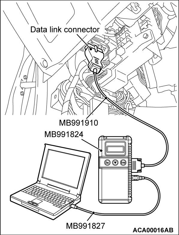
STEP 10. Using scan tool MB991958, read the diagnostic trouble code (DTC).
| caution | To prevent damage to scan tool MB991958, always turn the ignition switch to the "LOCK" (OFF) position before connecting or disconnecting scan tool MB991958. |
(1) Connect scan tool MB991958 to the data link connector.
(2) Turn the ignition switch to the "ON" position.
(3) After the DTC has been deleted, read the DTC again.
(4) Turn the ignition switch to the "LOCK" (OFF) position.
Is DTC P0606 set?
STEP 11. Using scan tool MB991958, read the diagnostic trouble code (DTC).
| caution | To prevent damage to scan tool MB991958, always turn the ignition switch to the "LOCK" (OFF) position before connecting or disconnecting scan tool MB991958. |
(1) Connect scan tool MB991958 to the data link connector.
(2) Turn the ignition switch to the "ON" position.
(3) After the DTC has been deleted, read the DTC again.
(4) Turn the ignition switch to the "LOCK" (OFF) position.
Is DTC P0606 set?
 Retry the troubleshooting.
 The inspection is complete.
![[Previous]](../../../buttons/fprev.png)
![[Next]](../../../buttons/fnext.png)
