DTC P1240: Ignition Angle
TECHNICAL DESCRIPTION
Checks for an abnormal ignition timing retard angle demand signal from the active stability control (ASC).
DTC SET CONDITIONS
Check Condition
- Ignition switch is "ON" position.
Judgment Criterion
- The ignition timing retard angle demand signal is not normal.
FAIL-SAFE AND BACKUP FUNCTION
- Ignition retard is not carried out.
TROUBLESHOOTING HINTS (The most likely causes for this code to be set are:)
- ASC system failed.
- ECM failed.
DIAGNOSIS
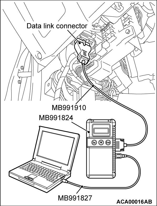
Required Special Tool:
- MB991958: Scan Tool (M.U.T.-III Sub Assembly)
- MB991824: V.C.I.
- MB991827: USB Cable
- MB991910: Main Harness A
STEP 1. Using scan tool MB991958, read the diagnostic trouble code (DTC).
| caution | To prevent damage to scan tool MB991958, always turn the ignition switch to the "LOCK" (OFF) position before connecting or disconnecting scan tool MB991958. |
(1) Connect scan tool MB991958 to the data link connector.
(2) Turn the ignition switch to the "ON" position.
(3) Read the ASC-DTC.
(4) Turn the ignition switch to the "LOCK" (OFF) position.
Is the ASC-DTC set?
STEP 2. Using scan tool MB991958, read the diagnostic trouble code (DTC).
(1) Turn the ignition switch to the "ON" position.
(2) Read the DTC.
(3) Turn the ignition switch to the "LOCK" (OFF) position.
Is the diagnostic trouble code other than P1240 set?
STEP 3. Using scan tool MB991958, read the diagnostic trouble code (DTC).
(1) Turn the ignition switch to the "ON" position.
(2) After the DTC has been deleted, read the DTC again.
(3) Turn the ignition switch to the "LOCK" (OFF) position.
Is DTC P1240 set?
![[Previous]](../../../buttons/fprev.png)
![[Next]](../../../buttons/fnext.png)


