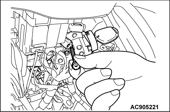
Removal of instrument panel cover lower assembly (Refer to GROUP 52A - Instrument lower panel )
Removal of steering column lower cover and steering column upper cover (Refer to GROUP 37 - Steering Shaft .)
Post-installation operation
Installation of steering column lower cover and steering column upper cover (Refer to GROUP 37 - Steering Shaft .)
Installation of instrument panel cover lower assembly (Refer to GROUP 52A - Instrument Lower Panel .)
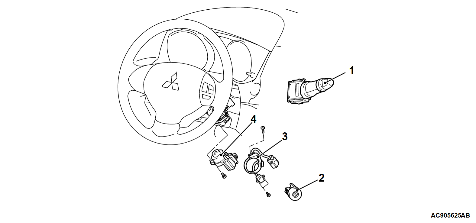
Removal Steps
1.
Wiper/washer switch (with built-in column-ECU)
<<A>>
2.
Steering lock hole
3.
Key reminder switch and key ring antenna assembly
4.
Ignition switch
note
Other than the single unit supplying of key reminder switch and key ring antenna assembly as well as of ignition switch, they are also supplied as the mechanical steering lock assembly (mechanical steering lock, steering lock bracket, steering lock bolt, key reminder switch and key ring antenna assembly, and ignition switch are supplied as a set). For how to remove the mechanical steering lock, steering lock bracket, and steering lock bolt, refer to GROUP 37 - Disassembly and Reassembly of Steering Shaft .
REMOVAL SERVICE POINT
<<A>> STEERING LOCK HOLE REMOVAL
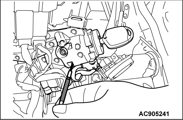
1. Insert the key into the steering lock hole, and turn the ignition key to the ACC position.
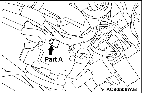
2. Using a flat-tipped precision screwdriver or similar tool, press the lock button located at the part "A" shown in the figure.
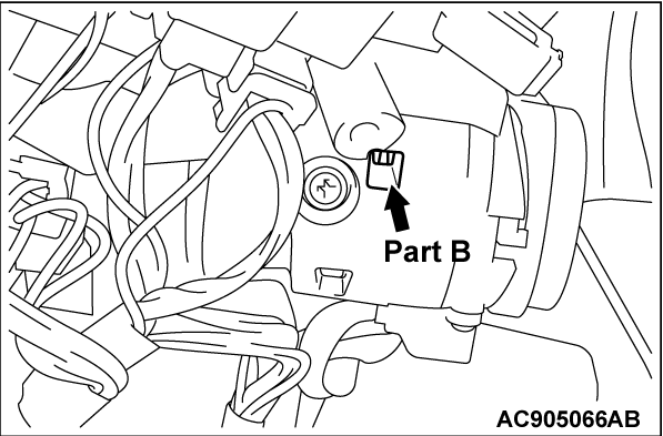
3. Subsequently, using a flat-tipped precision screwdriver or similar tool, press the step generated at the part "B" toward the direction of front passenger's seat. Then, pull out the ignition key, and then remove the steering lock hole.