![[Previous]](../../../BUTTONS/fprev.png)
![[Next]](../../../BUTTONS/fnext.png)
INSTRUMENT PANEL
REMOVAL AND INSTALLATION
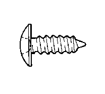
For installation of the instrument panel, the bolts and screws described below are used. They are indicated by symbols in the illustration.
|
NAME |
SYMBOL |
SIZE mm (in.) (D x L) |
COLOR |
SHAPE |
| Tapping screw |
A |
4 x 12 (.16 x .47) |
- |
 |
| B |
5 x 10 (.20 x .40) |
- |
| C |
5 x 12 (.20 x .47) |
- |
| D |
5 x 16 (.20 x .62) |
- |
| E |
5 x 12 (.20 x .47) |
- |
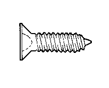 |
| F |
5 x 16 (.20 x .62) |
Black |
| G |
5 x 20 (.20 x .79) |
Black |
| H |
5 x 12 (.20 x .47) |
- |
|
| I |
5 x 6 (.20 x .62) |
Black |
|
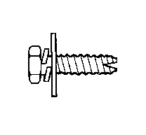
| Screw with washer |
J |
4x 12 (.16 x .47) |
- |
|
| K |
5 x 16 (.20 x .62) |
- |
|
| Bolt with washer |
L |
6 x 16 (.24 x .62) |
- |
 |
| M |
6 x 16 (.24 x .62) |
- |
| N |
6 x 12 (.24 x .47) |
- |
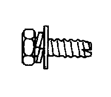 |
| O |
6 x 16 (.24 x .62) |
- |
| P |
8 x 20 (.31 x .79) |
- |
|
|
D = Thread diameter
L = Effective thread length