Safety Recall

SUBJECT:

PARKING BRAKE CORROSION - SAFETY RECALL CAMPAIGN - REVISED

No: SR-18-002REVII

DATE: June 2018

MODEL: See Below

CIRCULATE TO:

[ X ] GENERAL MANAGER

[ X ] PARTS MANAGER

[ X ] TECHNICIAN

[ X ] SERVICE ADVISOR

[ X ] SERVICE MANAGER

[ X ] WARRANTY PROCESSOR

[ X ] SALES MANAGER

This bulletin supersedes SR-18-002REV, to revise the ordering part number for the brake fluid and the approximate brake fluid (in fluid ounces). Revisions are italicized and indicated by Revision.

PURPOSE

This campaign bulletin instructs dealers to inspect the rear brake calipers and, if necessary, replace the parking brake boot and lever or the brake caliper body. On certain affected vehicles, the dealer must also replace the piston assembly and piston boot.

BACKGROUND

(A) Due to insufficient rust prevention to the operating shaft of the parking brake and insufficient sealing performance of the rear brake caliper lever boot, water may penetrate the brake caliper lever boot and the parking brake operating shaft, causing caliper body and/or parking brake operating shaft corrosion. As a result, the operating shaft may bind, causing the rear brakes to drag and/or decrease parking brake performance.

(B) Due to an inappropriate manufacturing process, the automatic adjuster in the rear brake caliper, with built-in parking brake, may not work. If the automatic adjusters do not work, as brake pads wear, the parking brake lever's effective engagement point will increase until the parking brake no longer engages.

If the parking brake does not operate properly, the vehicle, when parked on a slope, may move unexpectedly, increasing the risk of a crash.

AFFECTED VEHICLES

Certain 2014 - 2016 Outlander built April 12, 2013 - February 02, 2016
Certain 2013 - 2016 Outlander Sport built July 20, 2012 - July 08, 2016

520069620_floating0

REQUIRED OPERATIONS

Before starting this campaign procedure, CHECK THE WARRANTY SUPERSCREEN to verify if the vehicle is an affected VIN for this campaign and that this campaign procedure has not already been completed. The repair procedure is VIN-specific. If the vehicle has Campaign Operation C1802X or C1803X, follow Workflow A. If the vehicle has Campaign Operation C1802Z or C1803R, follow Workflow B.

CUSTOMER NOTIFICATION

Letters will be sent to all owners of affected vehicles requesting them to bring their vehicle to a local Authorized Mitsubishi dealer to have their vehicle remedied. Copies of the customer notification letters appear at the end of this bulletin.

REQUIRED EQUIPMENT

520069620_At Anchor5

520069620_At Anchor4

INSPECTION AND IDENTIFYING IMPROVED PARTS

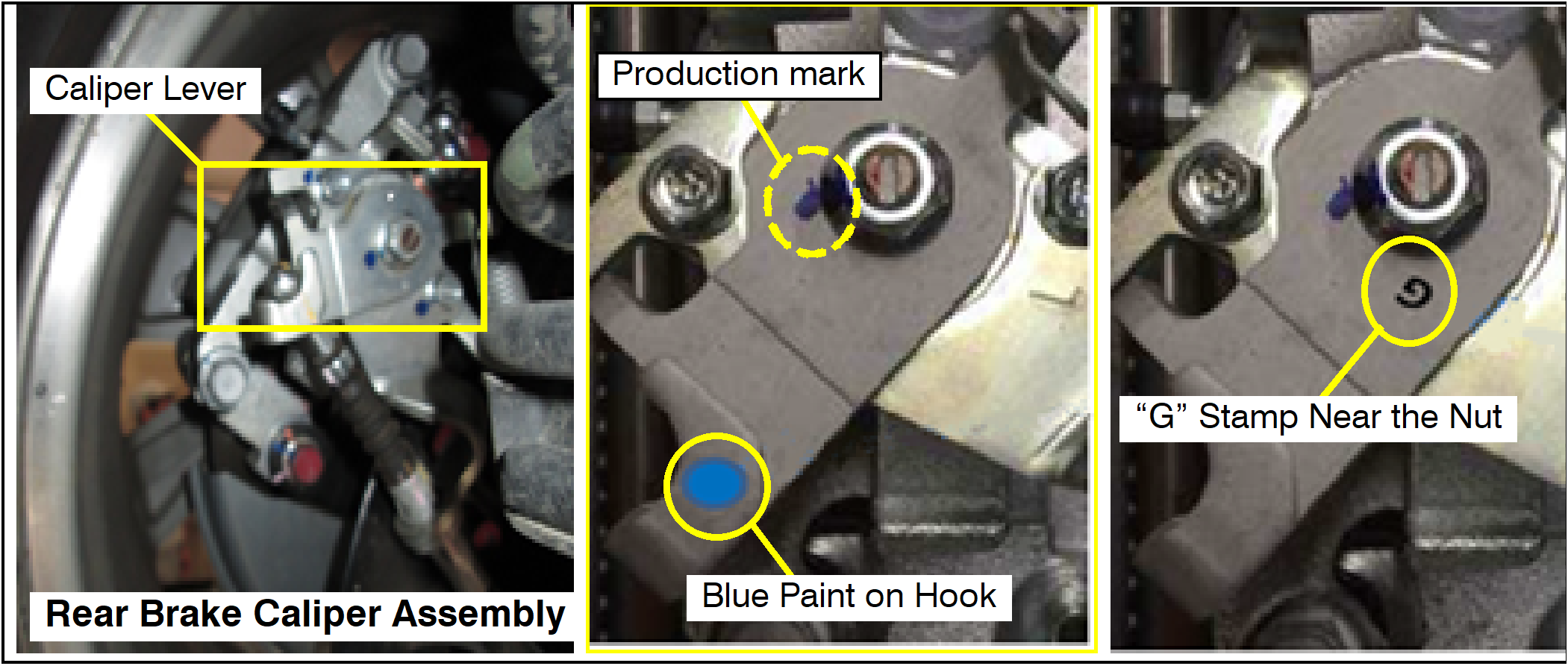
The affected parts may have already been replaced with improved parts even if the vehicle is listed as a campaign-affected vehicle. Check for identification marks on the caliper lever of the rear brake caliper assembly to determine whether the repair/replacement procedures are required.

If blue paint mark is found on the hook of the caliper lever or if “G” is stamped near the nut, the caliper is already a countermeasure unit. No further inspection or replacement work is required.

Check both left and right rear brake caliper assemblies.

NOTE: Blue or green marks located on areas other than the lever hook are production marks and do not mean they are improved parts.
520069620_graphic-text1E0

INSPECT CALIPER CLEARANCE AND STICKING

520069620_graphic-text1D0
  1. Ensure the ignition is OFF and the vehicle is on a level surface.
  2. Release the parking brake.
  3. Remove the rear floor console front panel assembly.
  4. Loosen the adjusting nut to allow slack in the parking brake cables.
  5. Raise the vehicle.
  6. Remove rear left and rear right tires.
520069620_graphic-text1D1
  1. Inspect the clearance between the Caliper Lever and Stopper.
    1. If the rear brake caliper lever is not in original position (clearance between the lever and stopper is more than 2 mm) when the parking lever inside the cabin is released, replace caliper body assembly.
    2. If the clearance between the lever and stopper is less than 2 mm, but the rear brake caliper lever will not return to the original position when the caliper lever fixing nut is turned using a box end wrench and released, or if the lever is stiff to return when manually operated, replace caliper body assembly.
520069620_graphic-text1D2
  1. If the caliper lever is at the original position (clearance between the lever and stopper is less than 2 mm), and the caliper lever smoothly returns to position, proceed to INSPECT OPERATING SHAFT AND CALIPER BODY GROOVE (page 8).

REMOVE CALIPER BODY - (ONLY IF VEHICLE REQUIRES PISTON REPLACEMENT [C1802Z OR C1803R] OR CALIPER BODY ASSEMBLY REPLACEMENT)

520069620_At Anchor3

Caution! Do NOT spill any brake fluid on vehicle or vehicle components.

Warning! Do NOT pinch or bend the brake hose.

520069620_graphic-text1C0
  1. Carefully, while not allowing brake fluid to spill onto vehicle or vehicle components, disconnect the brake hose from the caliper. Use a brake fluid stopper on the disconnected brake hose.
  2. Remove caliper body assembly mounting bolts.
  3. Remove caliper body assembly from caliper support.


INSPECT OPERATING SHAFT AND BODY CALIPER GROOVE

520069620_graphic-text1B0
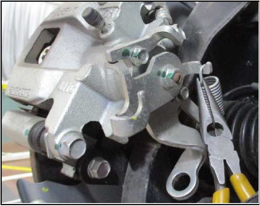
  1. Unhook the spring from the lever, using needle nose pliers.

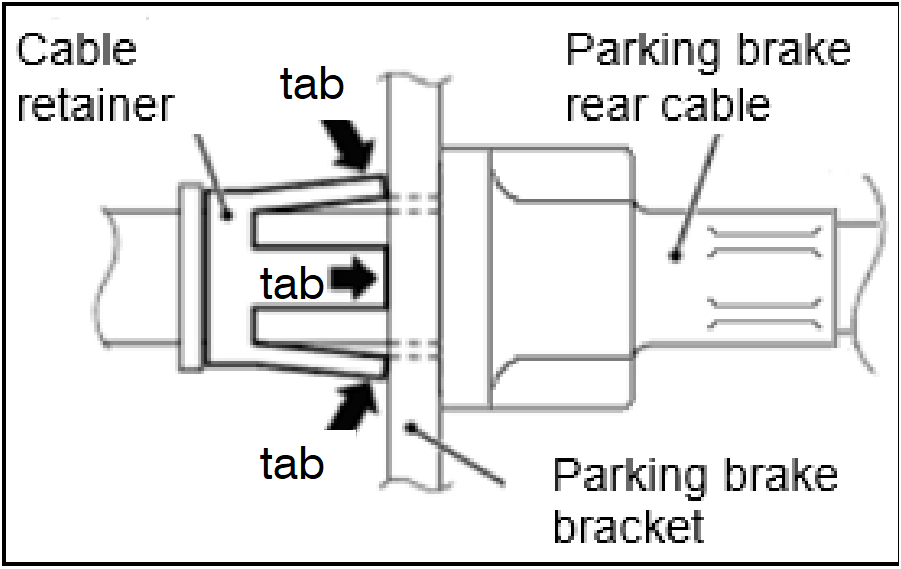
Caution! When disconnecting the parking brake rear cable, be careful not to damage the tabs located on the retainer of the parking brake rear cable. Fit a 12.8 mm (0.5 in) hose clamp (MB248923) on the retainer of the parking brake rear cable will prevent damage to tabs during tabs compression.
520069620_graphic-text1A0
  1. Fit a hose clamp over the parking brake cable retainer.

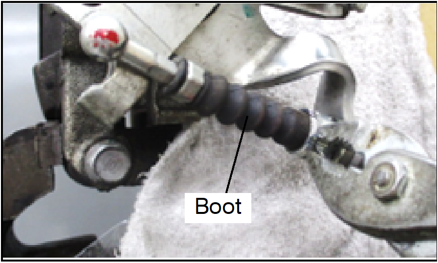
Caution! Be careful to not damage the boot while pulling the parking brake rear cable off of the parking brake bracket.
520069620_graphic-text190
  1. Remove the parking brake cable.
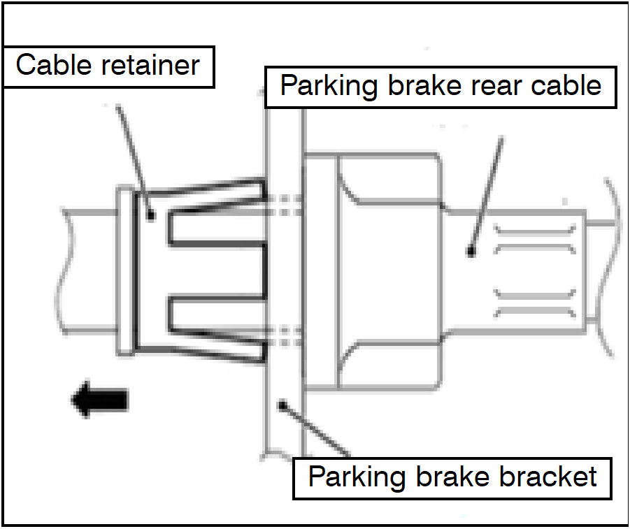
    1. Compress the tabs located on the retainer of the rear parking brake cable, and pull the parking brake rear cable off of the parking brake bracket of the rear brake caliper assembly.
520069620_graphic-text180
  1. Clamp the caliper body assembly with a vise, at the illustrated section. (Only if caliper body has been removed, on page 7.)

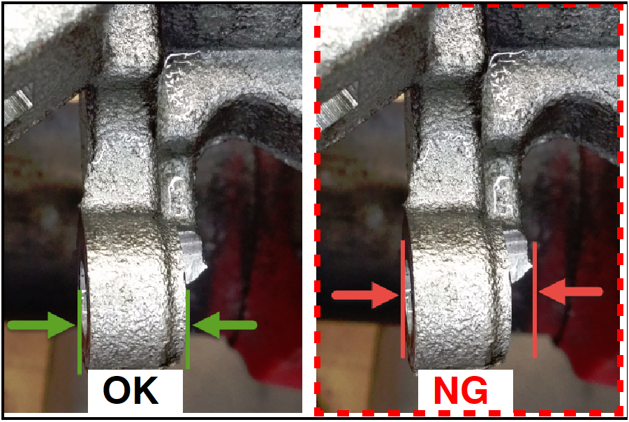
CAUTION: DO NOT fix the caliper body assembly at the stepped section (NG).

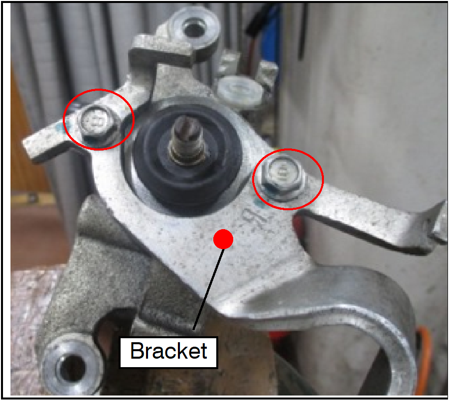
Warning! Risk of Injury. Force is required to remove the caliper lever as it is press-fitted. Ensure that the circled nut is loosened and not completely removed in the next step.
520069620_graphic-text170
  1. Loosen, but do not remove, the nut.

NOTE: To prevent the caliper lever from rotating, fix the stopper on the bracket and lever with an adjustable wrench or locking pliers.

520069620_graphic-text171
  1. Insert (2) slotted screwdrivers diagonally, and remove the lever by lifting it with the tips of the screwdrivers.

NOTE: Cover the tip of the slotted screwdrivers with clean rags to prevent damage to the bracket.

  1. Remove, but keep the nut for temporary reuse.
  2. Remove and discard the caliper lever.
520069620_graphic-text160
  1. Unbolt and remove the bracket.
520069620_graphic-text161

(After bracket removal.)

520069620_graphic-text162
  1. Remove the lever boot.
520069620_graphic-text150
  1. Wipe off grease and dirt.
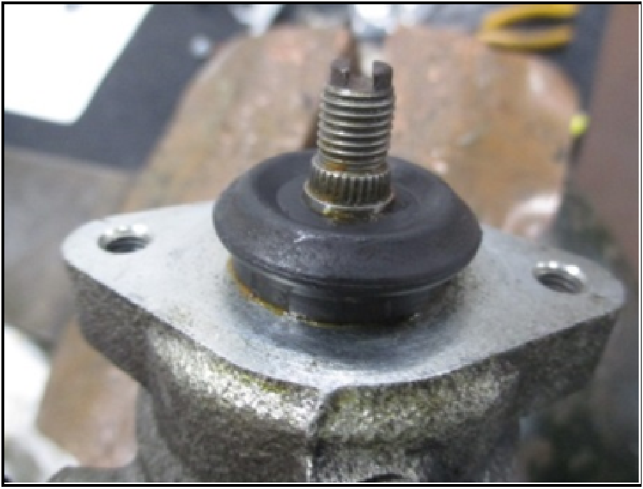
    1. Wipe the operating shaft (1), the hole in the caliper body (2), the caliper body groove (3), and the caliper bracket installation surface (4) with clean rags.

NOTE: Do not spray cleaner directly onto the parts.
If using cleaner, spray it onto rags first, then use rags to wipe off grease and dirt. This is to prevent swelling of the rubber seal (o-ring) located at the end of the operating shaft in the hole of the caliper body.

520069620_graphic-text151
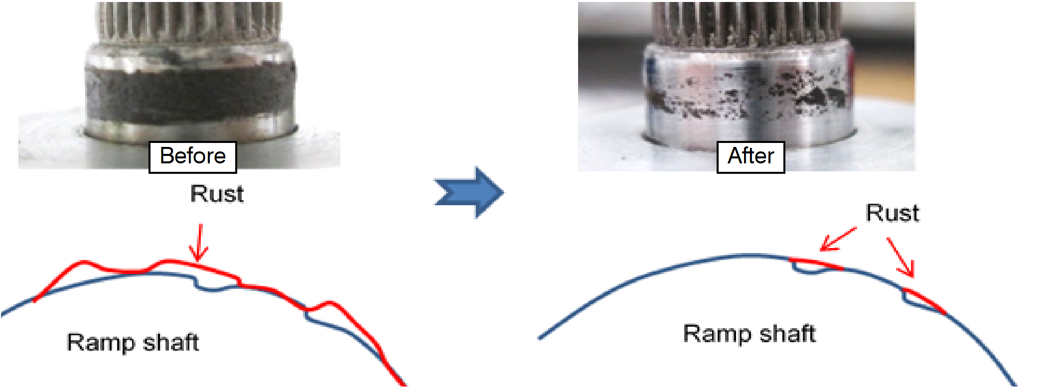
  1. Evaluate the rust condition of the operating shaft and caliper body groove.
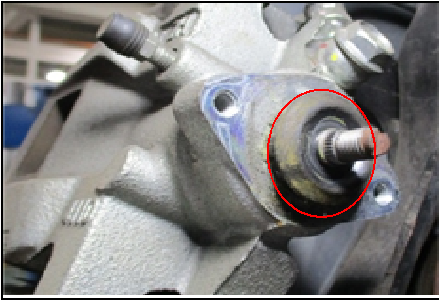
    1. From the operating shaft, if rust has not reached the caliper body surface and no rust is observed on the flange surface inside the boot, the condition is acceptable. Proceed to REPLACE CALIPER LEVER AND LEVER BOOT (page 12).
520069620_graphic-text140
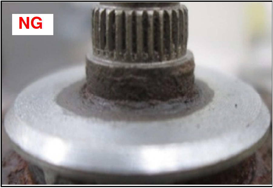
  1. If rust has reached the caliper body surface and/or rust is observed on the flange surface inside the boot, obtain a new Caliper Body Assembly and proceed to INSTALL CALIPER BODY ASSEMBLY (page 25).

NOTE: The condition must be evaluated as NG if any scarring is found on the operating shaft (1) or near the caliper body groove.

REPLACE CALIPER LEVER AND LEVER BOOT

Identify the parts required for the following procedure.
520069620_At Anchor2

520069620_graphic-text130
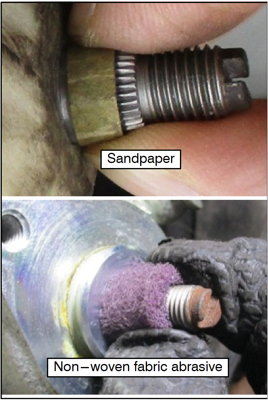
  1. Remove the rust on the operating shaft. (Only for cases determined to be “OK” in the evaluation on page 11.)
    1. Remove loose rust using a stainless steel brush and wipe the part with clean rags. Wrap a piece of sandpaper (#400) cut in a strip, non-woven fabric abrasive (3M Scotch-Brite #400), or similar, around the shaft, and rotate it to remove the rust that has built up on the operating shaft surface.
  2. Clean the operating shaft's thread with a wire brush.
  1. Polish until the surface rust is removed and the surface feels smooth. There is no need to scrape off the rust that eroded the operating shaft surface. To finish, clean the abrasive powder using an air gun or clean rags.
520069620_graphic-text120
520069620_graphic-text110
  1. Apply grease, included in the lever and boot kit, onto the caliper body around where the operating shaft is inserted, and set the O-ring, included in the lever and boot kit, onto the operating shaft.

NOTE: Make sure no contaminants are present.

NOTE: When applying grease, make sure that it does not go into the threaded bracket mounting holes. Mask the threaded bracket mounting holes, if necessary.

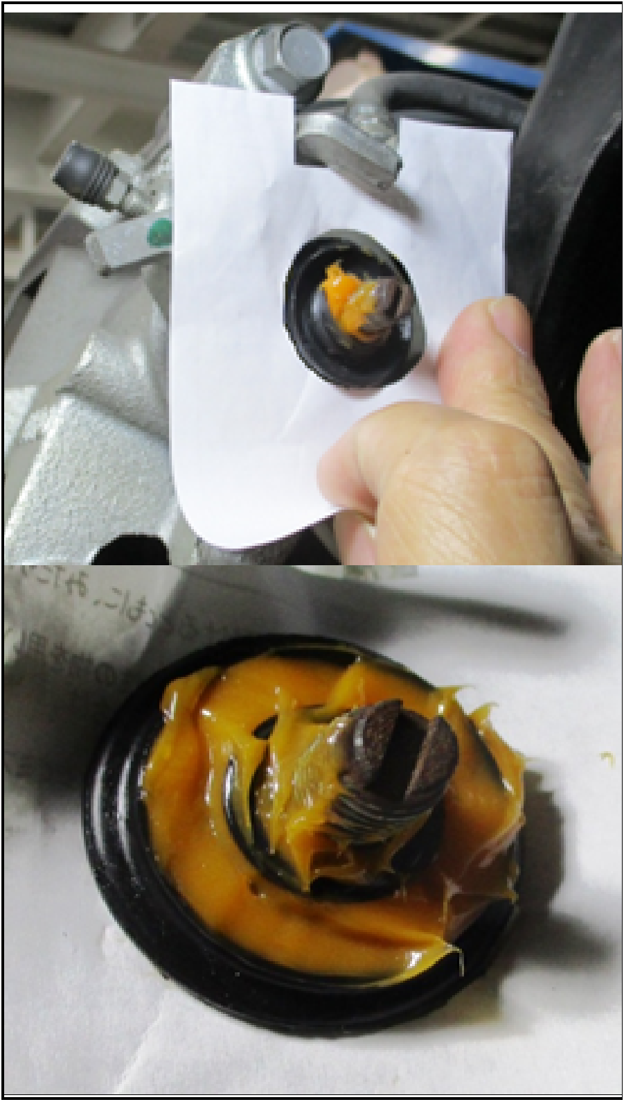
  1. Fill inside the lever boot with grease (0.5 g), included in the lever and boot kit, and apply the same grease to the outer circumference of where it mates with the body groove.
520069620_graphic-text100
520069620_graphic-text101
  1. Securely fit the lever boot to the caliper body groove, and rotate the boot to confirm that it is correctly fitted.
  2. Using clean rags, wipe excess grease off of the bracket installation surface.
520069620_graphic-text102
  1. Install the bracket.
  • Flange bolt tightening torque: 70 to 103 in-lb (7.85 to 11.7 Nm)
520069620_graphic-textF0
  1. Use a masking sheet to prevent grease from spreading to the surrounding surfaces and apply grease on the outside of the lever boot (0.5 g).


  2. Apply grease to the dipped portion and outer lip of the outer surface of the lever boot.
  3. Remove the masking sheet.
520069620_graphic-textE0
  1. Set the new caliper lever to the original position, apply grease to the thread of the operating shaft, pre-assemble the caliper lever using the original nut that was removed during step 7 of the INSPECT OPERATING SHAFT AND BODY CALIPER GROOVE section (page 9).
    1. Confirm that grease has been applied to the thread of the operating shaft before tightening the nut.
      In order to lower the tightening torque, the nut is to be tightened only after grease has been applied to the threaded portion of the operating shaft.


    2. Fix the stopper and caliper lever with an adjustable wrench or locking pliers to prevent the operating shaft from rotating, and hand tighten the original nut until the caliper lever has been pushed onto the operating shaft's serration.

NOTE: Clean the operating shaft's thread with a wire brush if the original nut cannot be tightened by hand.

520069620_graphic-textE1
  1. Tighten the original nut (after grease application) to 21 ft-lb (29 Nm).

CAUTION: Do NOT apply torque that exceeds 22 ft-lb (30 Nm). Exceeding the specified torque may cause the operating shaft to break.

CAUTION: Do NOT use a hammer.

  1. Dispose of the remaining grease according to local regulations.
520069620_graphic-textD0
  1. Confirm that the caliper lever is at the original position after it is assembled. (The clearance between the lever and stopper must be 1 mm or less.)

NOTE: The lever cannot be reused. Dispose the lever if the clearance is larger than 1 mm.

  1. Confirm that the caliper lever is press-fitted to the operating shaft.
520069620_graphic-textD1
  1. Remove and discard the original nut, and wipe off the grease on the thread of the operating shaft with dry, clean rags.

NOTE: Do not spray cleaner directly onto the parts.
If using cleaner, spray it onto rags first, then use rags to wipe off grease and dirt. This is to prevent swelling of the rubber seal (O-ring) located at the end of the operating shaft in the hole of the caliper body.

520069620_graphic-textD2
  1. Fix the caliper lever using the new nut included in the lever & boot kit.
  • Tightening torque: 13 to 19.5 ft-lb (17.7 to 26.5 Nm)

WARNING: If the nut cannot be tightened to the specified tightening torque, it is possible that the operating shaft may be broken.
In that case, replace the caliper body assembly.

520069620_graphic-textC0

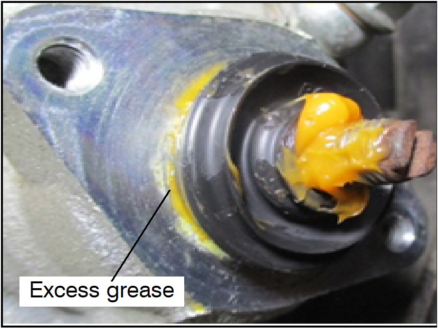
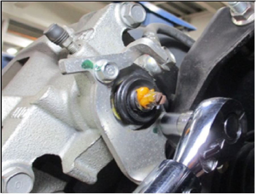
NOTE: There is no need to wipe off excess grease that flows out of the boot after the lever has been tightened
(Grease overflows as the boot is filled with a sufficient amount, and therefore, this is not an issue.)

520069620_graphic-textC1
  1. Install the spring.
520069620_graphic-textC2
  1. Engage the hook of the spring from “inside” to the “outside” direction.
  1. If vehicle does not require piston and piston boot replacement, go to REASSEMBLY AND PARKING BRAKE CABLE ADJUSTMENT section.

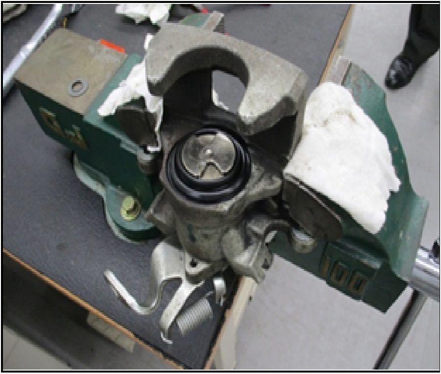
REPLACE PISTON ASSEMBLY AND PISTON BOOTS - (ONLY ON AFFECTED VEHICLES [C1802Z AND C1803R] AND WHERE THE CALIPER BODY IS NOT BEING REPLACED)

Identify the parts required for the following procedure.
520069620_At Anchor1

520069620_graphic-textB0
  1. Clamp the caliper body assembly in the vise.

CAUTION: When clamping the caliper body assembly with a vise, sandwich the caliper body with wood or rags, to prevent damage to the caliper body.

520069620_graphic-textA0
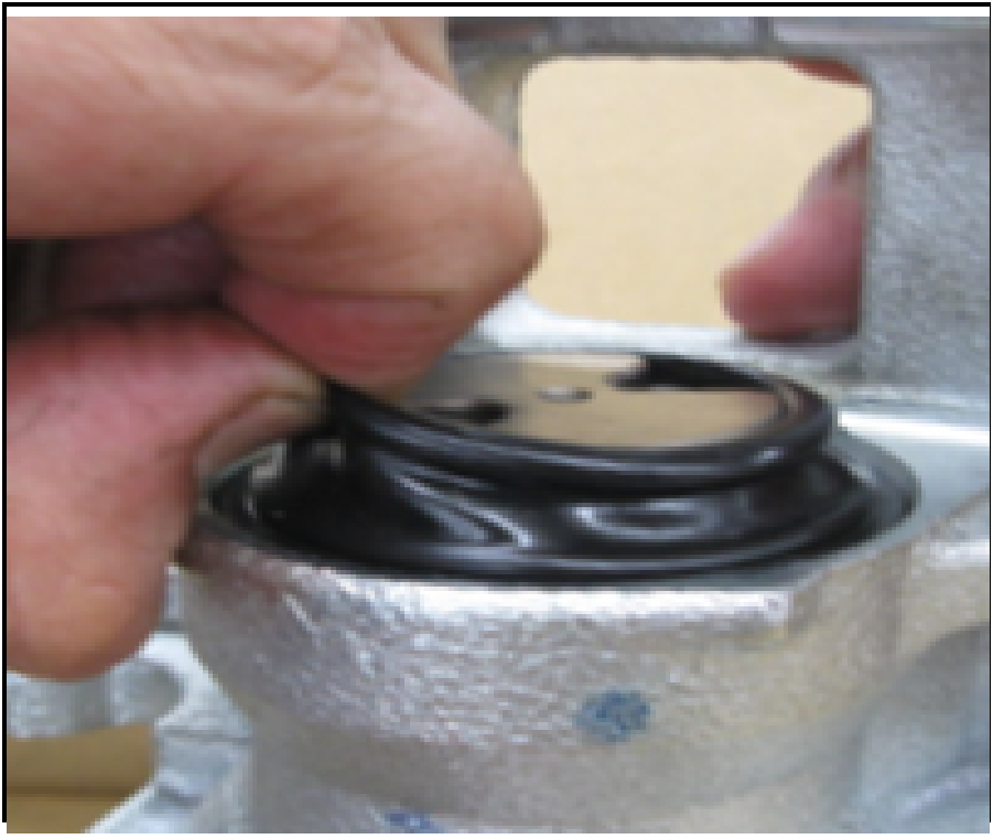
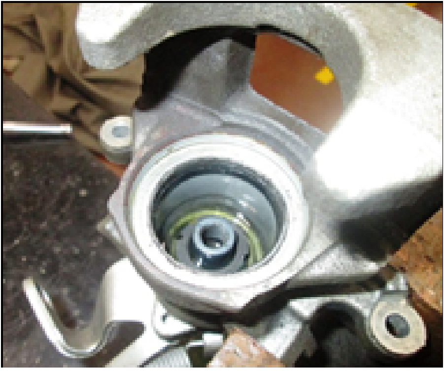
  1. Pull up the piston, pinch and remove the piston boot.
520069620_graphic-textA1
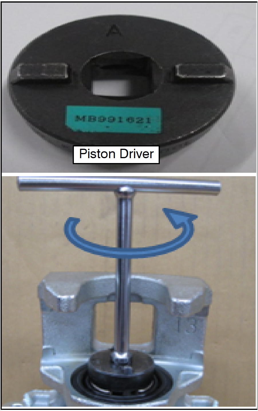
  1. Use a Piston Driver and rotate counterclockwise to remove piston assembly from the caliper.
520069620_graphic-text90
  1. Pull up and remove the piston.
520069620_graphic-text91

CAUTION: Do NOT allow any foreign materials to enter the caliper cylinder.

520069620_graphic-text80
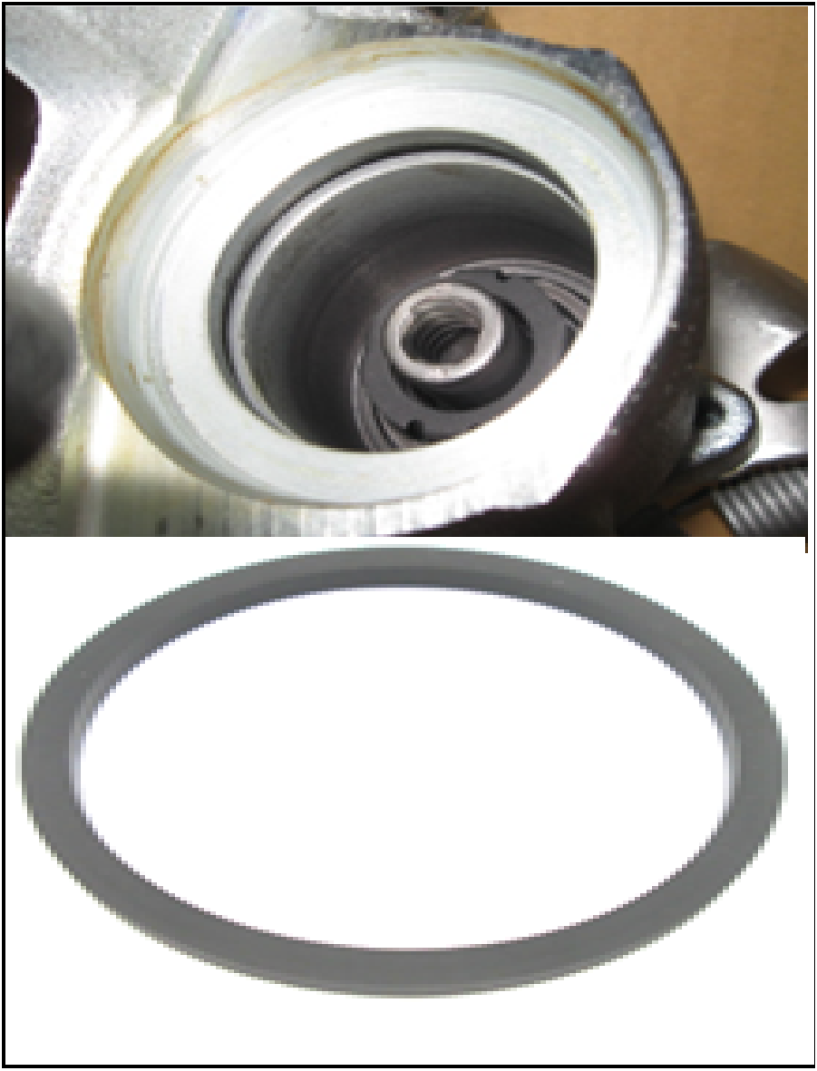
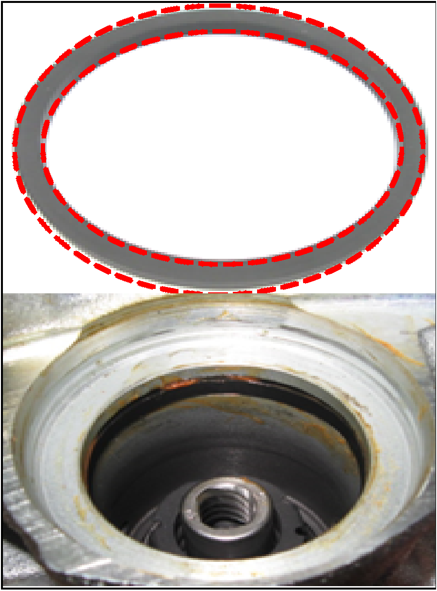
  1. Remove the piston seal.
520069620_graphic-text81
  1. Apply the grease in washer kit to the new piston seal, from kit, as shown on the dotted lines.
    1. Fit the new, greased seal into the gap.

CAUTION: Confirm that the seal is fully seated.

520069620_graphic-text70
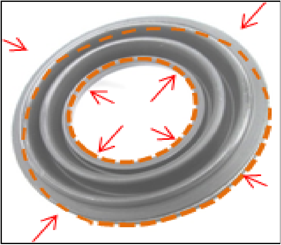
  1. Apply the grease to the inner and outer races of the piston boot, as shown on the dotted lines.
520069620_graphic-text60
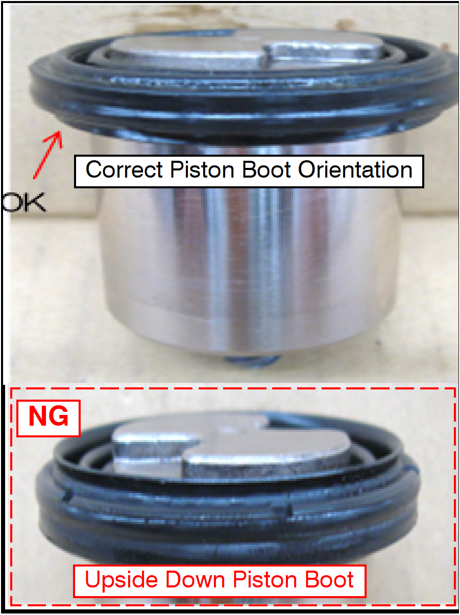
  1. Install the new piston boot to the piston assembly.

CAUTION: Do NOT install the piston boot upside down (NG).

  1. Use a Piston Driver to assemble the piston assembly to caliper body.
520069620_graphic-text50
520069620_graphic-text40
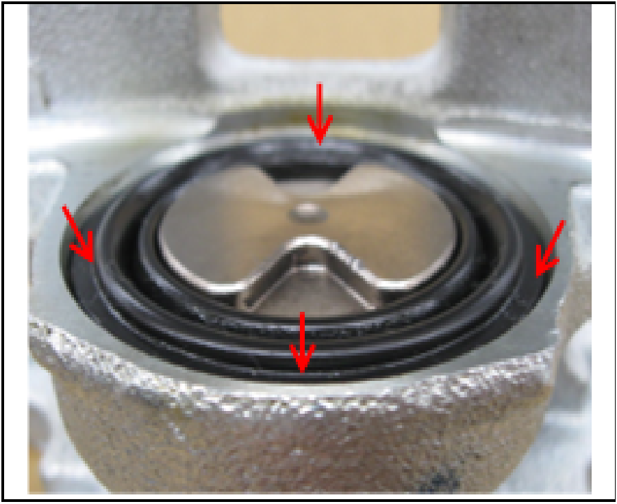
  1. Fit the piston boot outer race to the caliper body gap.
520069620_graphic-text41
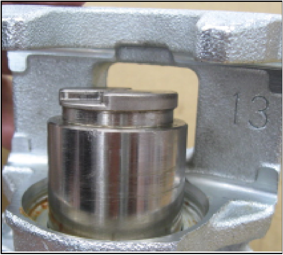
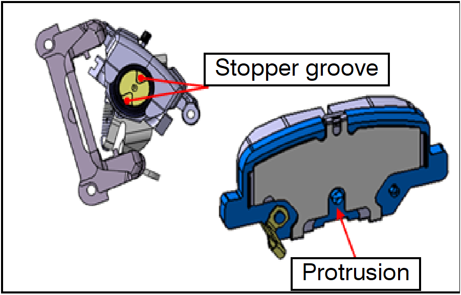
  1. Rotate the piston to the correct position.
  2. Ensure that the piston does not interfere with the brake pad assembly by ensuring that the brake pad assembly protrusion lines up with the piston stopper groove.

INSTALL CALIPER BODY ASSEMBLY

520069620_graphic-text30
  1. Install the parking brake rear cable (on the rear brake caliper assembly side).
    1. Put the retainer of the parking brake rear cable through the parking lever hole of the rear brake caliper assembly.
    2. Pull the parking brake rear cable in until it can be fixed at the retainer and engage the metal piece at the tip of the cable onto the caliper lever hook.
520069620_graphic-text31

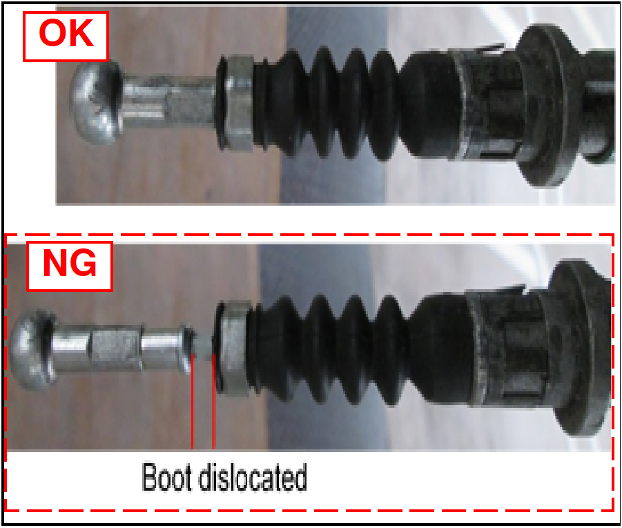
NOTE: Ensure that the boot is not dislocated.

520069620_graphic-text32
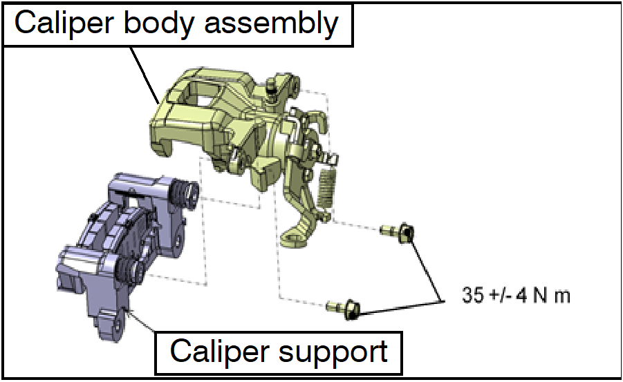
  1. Bolt the improved caliper body assembly to the caliper support on the vehicle side.
  • Flange bolt tightening torque: 26 ± 2 ft-lb (35 ± 4 Nm)
520069620_graphic-text20
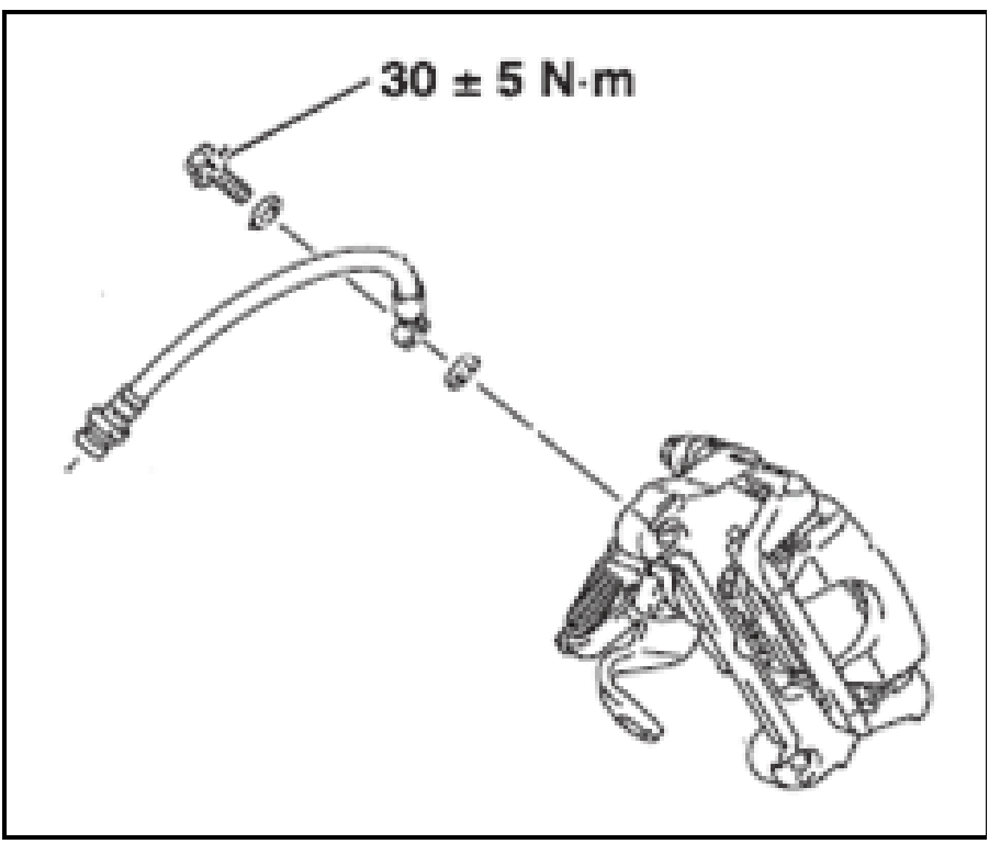
  1. Place new gaskets on both sides of the metal fitting of the brake hose and tighten the connector bolt.
  • Brake hose connector bolt tightening torque: 22 ± 3 ft-lb (30 ± 5 Nm)

Use DOT4 brake fluid.

Caution! Do NOT mix different types of brake fluid.

For Manual Transmission vehicles, ensure the fluid level is maintained above the clutch inlet line at all times.
520069620_graphic-text10
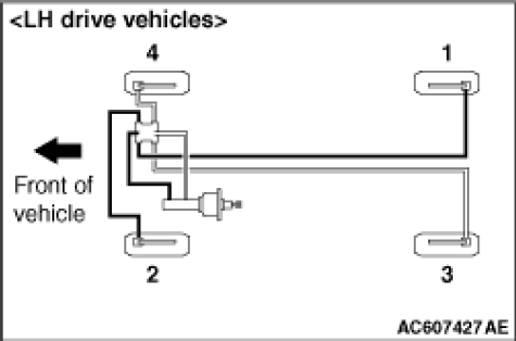
  1. Fill brake fluid and bleed air.
    1. Bleed air in the order specified in the drawing.
    • Bleeder screw torque: 70 ± 7 in-lb (7.9 ± 0.9 Nm)
  1. Start the engine and firmly depress the brake pedal two to three times.

NOTE: By depressing the brake pedal, the clearance between the brake pads and rear brake disc is adjusted to its optimum level.
The brake pedal should not sink to the floor while the engine is running. Perform troubleshooting to identify and repair any issues.

REASSEMBLY AND PARKING BRAKE CABLE ADJUSTMENT

  1. Turn the adjusting nut to adjust the parking brake lever travel to the standard value. After adjustment, check for looseness between the adjusting nut and parking brake lever.

Model

Outlander, Outlander Sport, RVR

Lever operating force

200 N (45 pounds)

Lever travel

6 to 7 notches

Do NOT set the parking brake lever travel to a value lower than the standard value as it will cause dragging of the rear brakes.

  1. After adjusting the parking brake lever travel, release the parking brakes and rotate the rear wheels to check for dragging of the rear brakes.
  2. Reinstall rear left and rear right tires.
  3. Check the parking brake force.
    1. With a brake tester: Confirm whether it satisfies the parking brake force specified in the service manual.
    2. Without brake tester: While the vehicle is lifted up and its parking brake lever pulled up 4 notches, assemble tires, torque the wheel nuts to 98 Nm, and confirm that the tires will NOT rotate. OR, engage the parking brakes while creeping to confirm that the vehicle can be stopped.

PARTS INFORMATION

Use only the Genuine Mitsubishi Parts listed below:

Part Number

Description

Qty

Note

4605B841

Caliper body assy (LH)

1


4605B842

Caliper body assy (RH)

1


4605B849

Caliper lever & Boots Kit (LH)

1


4605B850

Caliper lever & Boots Kit (RH)

1


4605B846

Washer Kit

1

(1) washer kit required per piston assembly.
(Washer from washer kit is not used)

4605C046

Piston assy

1

Only C1802Z and C1803R campaigns

4650B827QA

Gasket

2

(2) gaskets required for each caliper body installation

MZ341022RCL*

DOT4 Brake Fluid (to be used only for claims processing on this recall)

1

(1) per side when caliper or piston is replaced

Revision  *Order part number MZ320900 if additional brake fluid is required.

Recall Campaign Claim Information

Enter all claims as claim type ‘C’ – Recall/Campaign Claims

Please follow the campaign instructions when entering each claim. See the example below.

Certain 2013-2015 MY Outlander Sport (4A models only), 2014-2016 MY Outlander, 2016 MY Outlander Sport (JA models only).

Recall Claim Header Section

520069620_Auto1

After entering the required customer data and vehicle information, select the applicable campaign number and the one replacement scenario that was actually performed. Then, by hitting the “Save and Continue” button, the system will automatically fill-in several other fields.

Labor and Parts:

Labor: There are many possible repair scenarios for this campaign - follow the charts provided to select the appropriate labor operation and parts used for the repair performed.

520069620_At Anchor0

Rental Cars

If there is a need to provide the owner with a rental car, claim the applicable charges in this section

520069620_Auto0

NOTE: Rental cars applicable in the US and Puerto Rico only.

520069620_Page1

520069620_Page0

Copyright 2018, Mitsubishi Motors North America, Inc.

The information contained in this bulletin is subject to change. For the latest version of this document, go to the Mitsubishi Dealer Link, MEDIC, or the Mitsubishi Service Information website (www.mitsubishitechinfo.com).