A clicking noise (along with whining/humming), directly related to vehicle speed, is heard in the passenger compartment. As vehicle
speed increases, the clicking speed increases (engine speed has no effect on the noise). Due to engine
and road noises, the sound typically cannot be heard at vehicle speeds above 40 MPH.
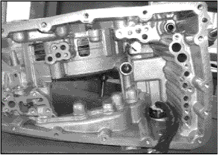
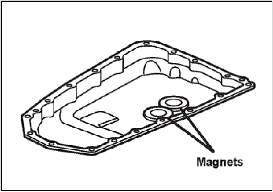
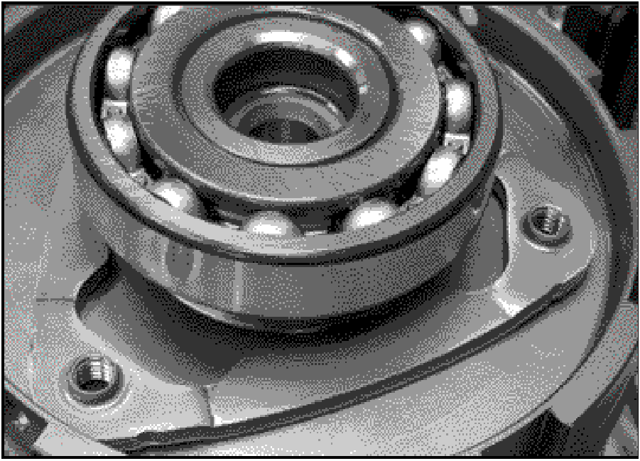
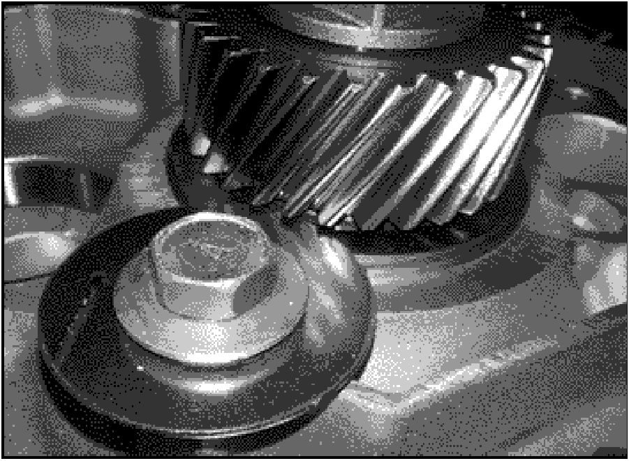
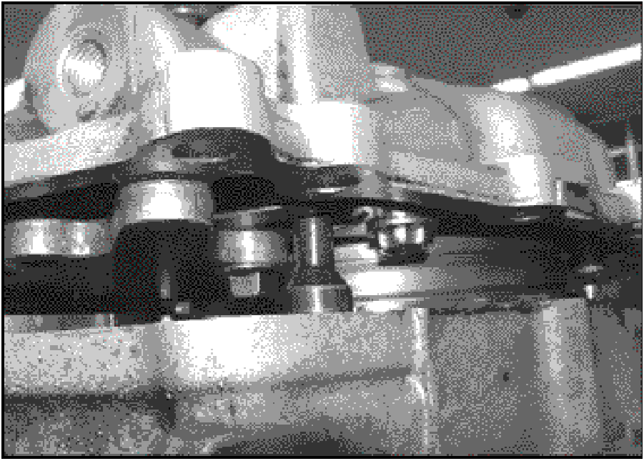
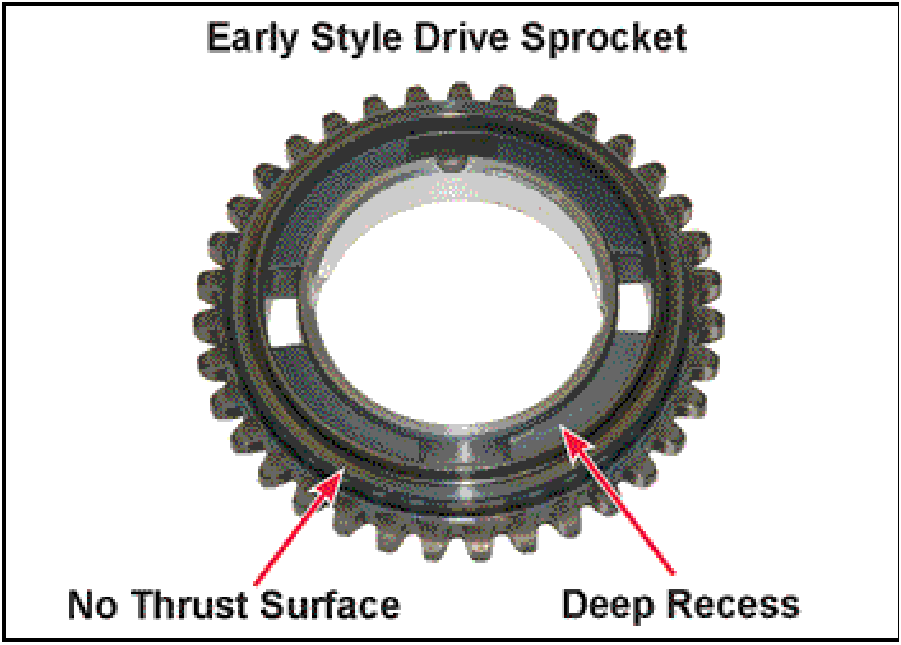
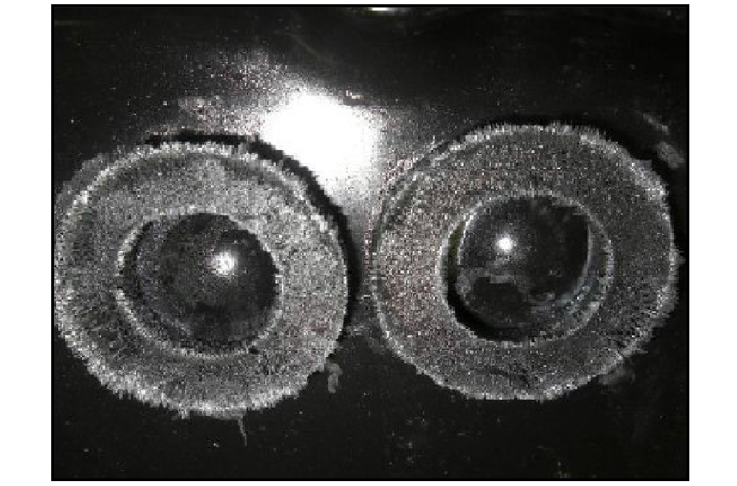
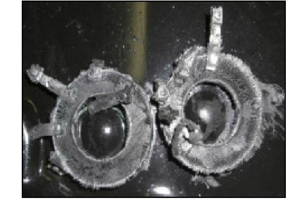
Prior to removal, drain the transaxle and remove the oil pan. Inspect the two magnets in the pan for debris
and foreign material. Compare the magnets to the photos below.
Following is a brief outline of the repair steps contained in this TSB. Specific procedures to be followed
after the transaxle has been removed begin on page 3.
In addition to the CVT special tools specified in the service manual Group 23B, the following tools are
required to complete this repair.
 |
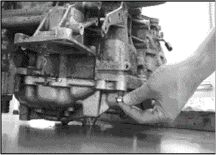
TRANSAXLE REMOVAL
With the transaxle still in the vehicle, unfasten the
control harness cable bracket from the dipstick.
Remove the dipstick and transaxle mount. Remove the
transaxle from the vehicle.
Before transaxle disassembly, always clean any debris
from the outside of the transaxle case.
- Remove the torque converter from the transaxle and
drain.
|
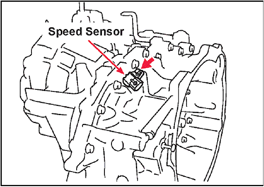 |
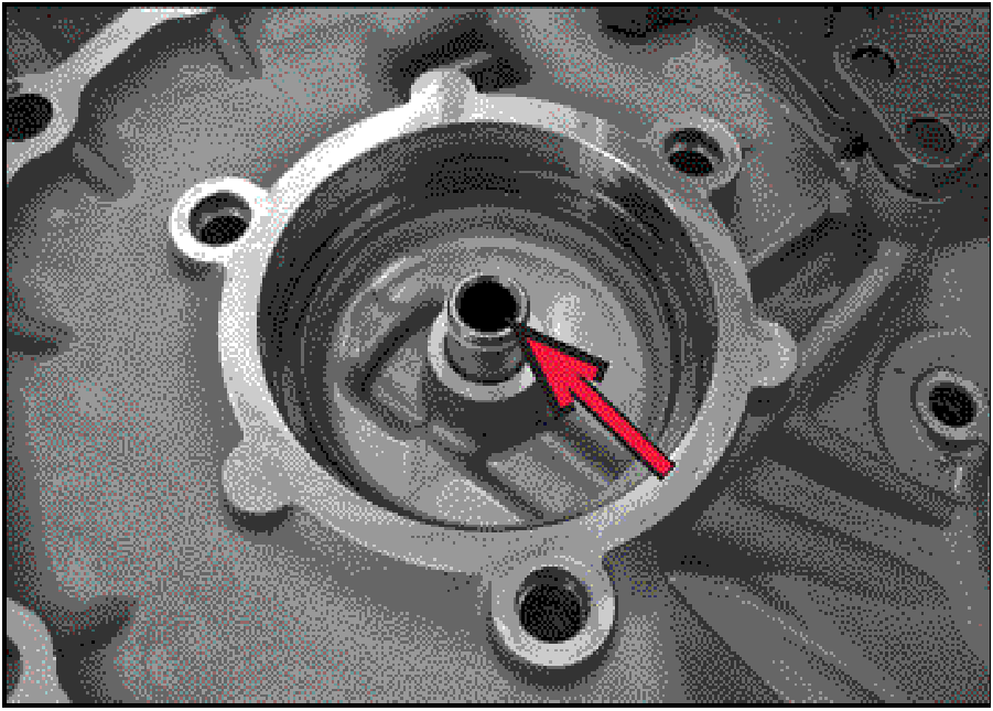
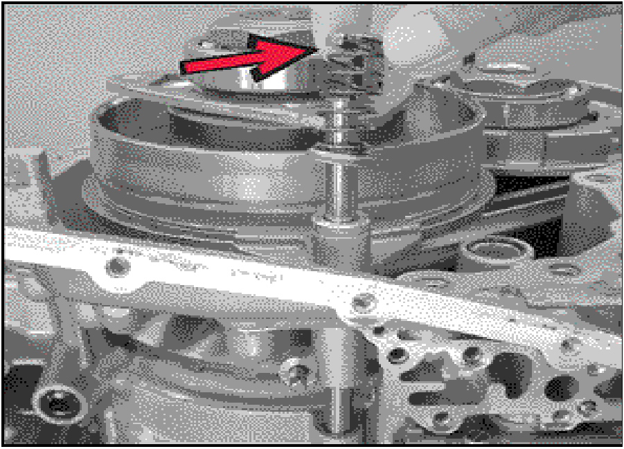
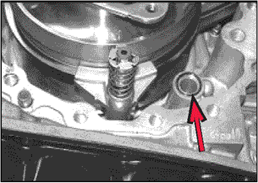
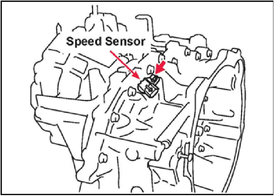
- Remove the secondary pulley speed sensor mounting
bolt
|
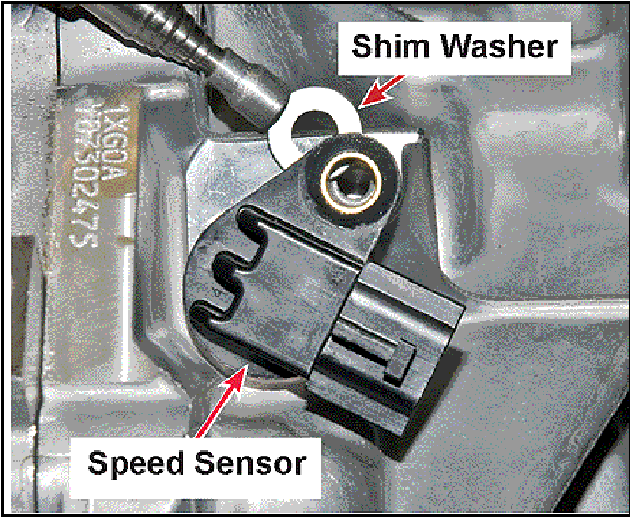 |
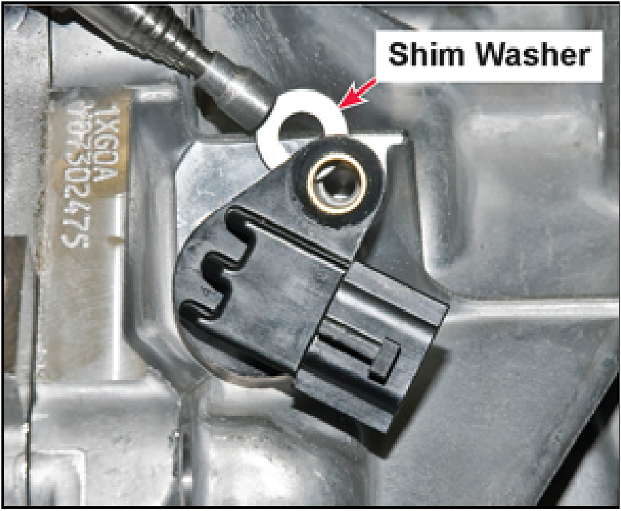
- At the same time the secondary pulley speed sensor
is being removed from the transaxle case, using a stick
magnet to remove the secondary pulley speed sensor
shim washer.
NOTE: If the shim washer is omitted, the speed
sensor will rub against the Secondary Pulley and
damage the tip of the sensor.
|
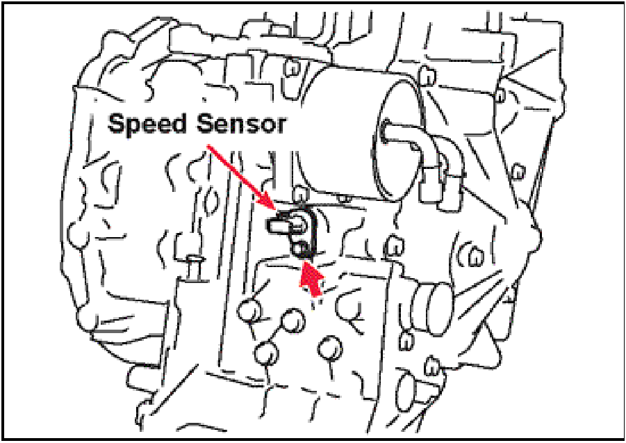 |
- Remove the primary pulley speed sensor.
|
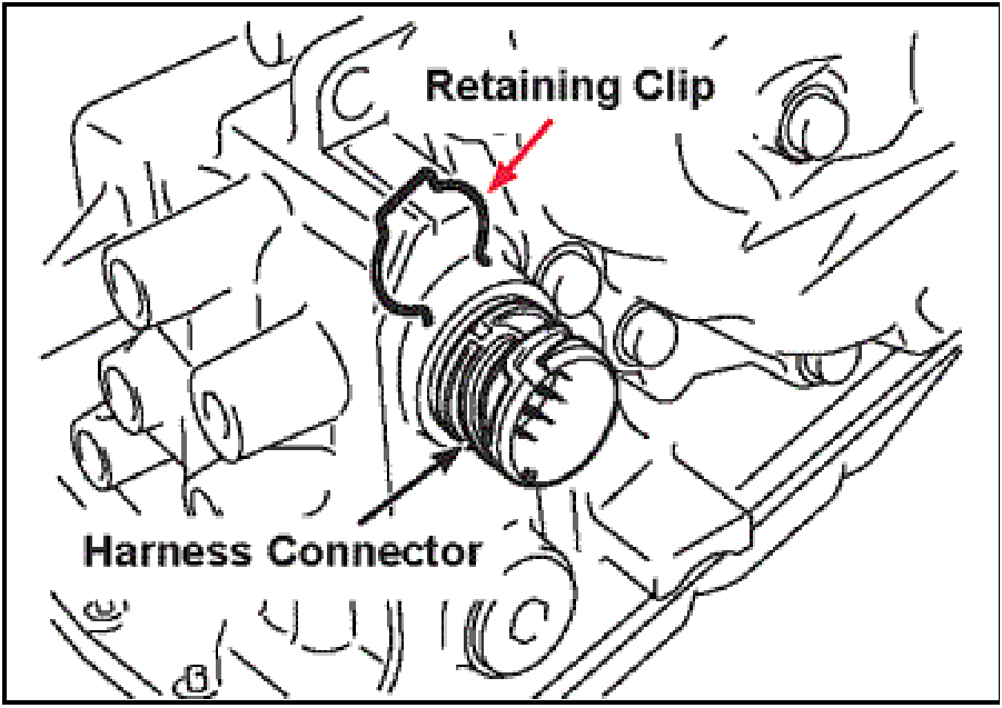 |
- Remove the retaining clip from the harness connector.
|
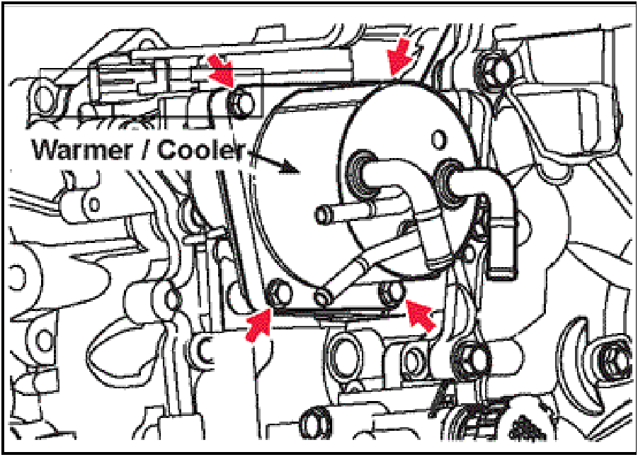 |
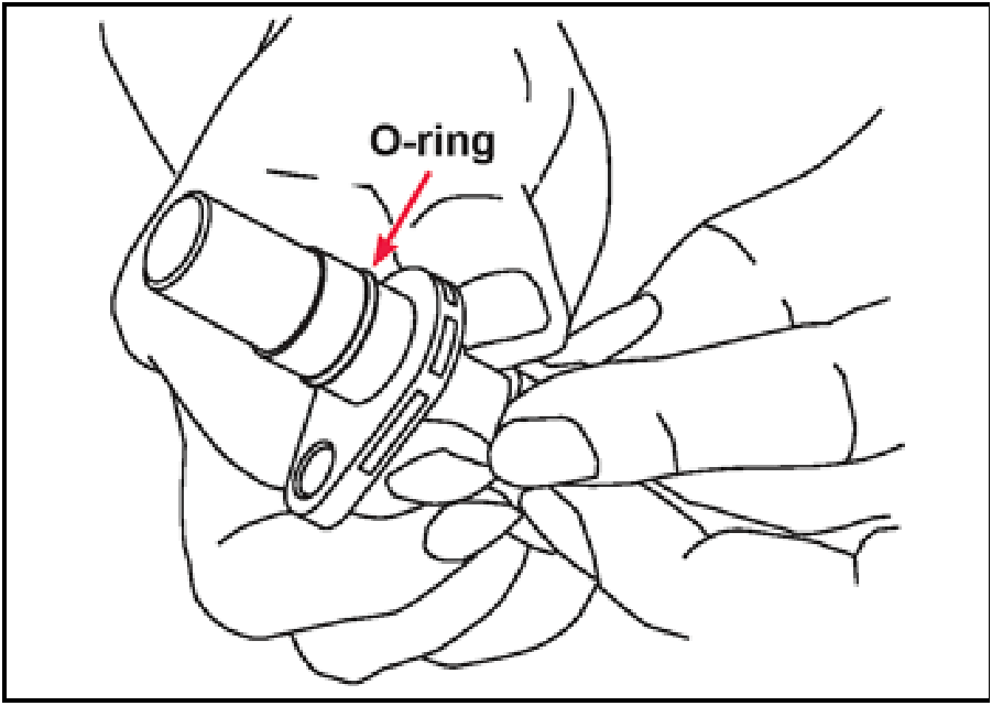
- Remove the warmer/cooler and large o-ring.
Discard the o-ring.

The aluminum tubes on the warmer/cooler are very
soft. Take care as not to bend, kink or crush them
in any way.
|
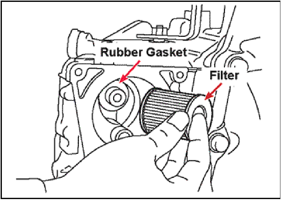 |
- Remove the ATF warmer/cooler filter and rubber seal
from the case and discard both.
NOTE: Verify the rubber filter seal comes out with
the filter.
|
 |
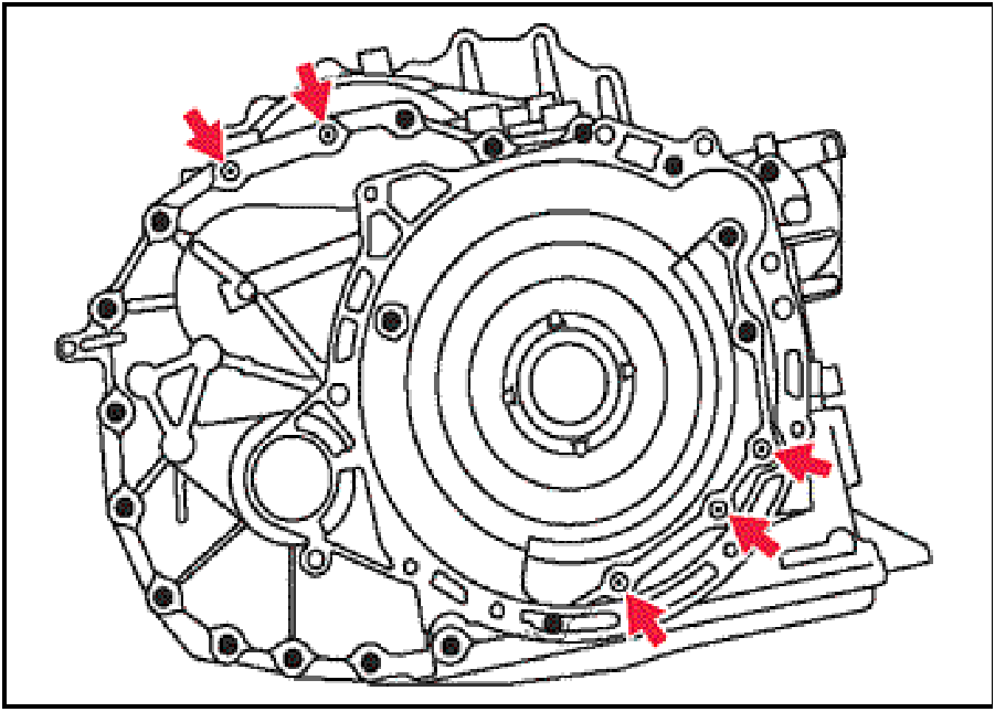
- Rotate the transaxle on the bench so the converter
housing faces up.
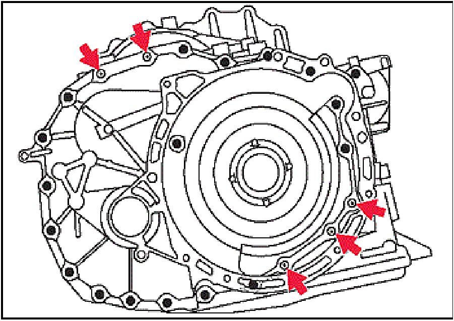
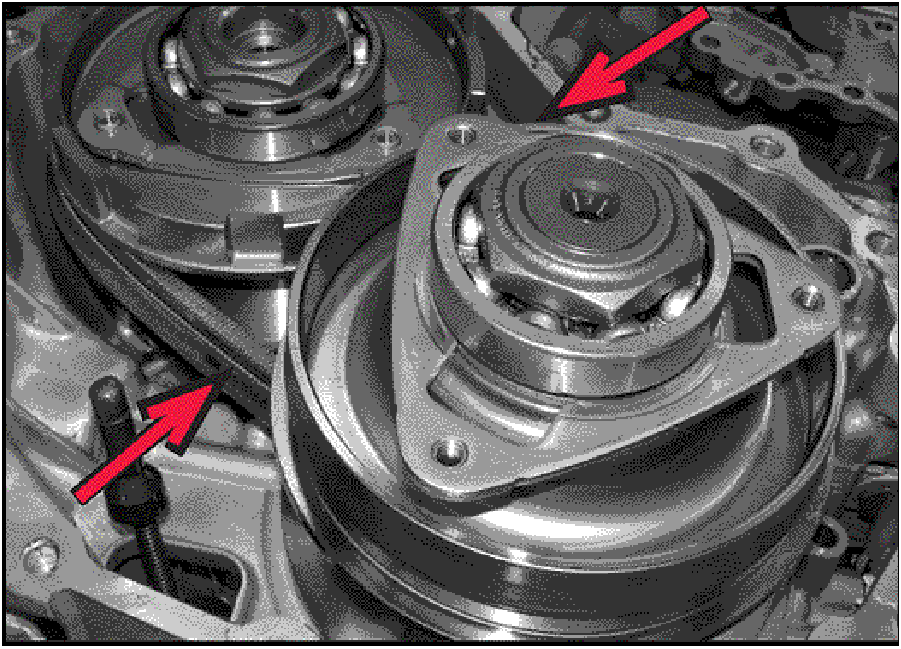
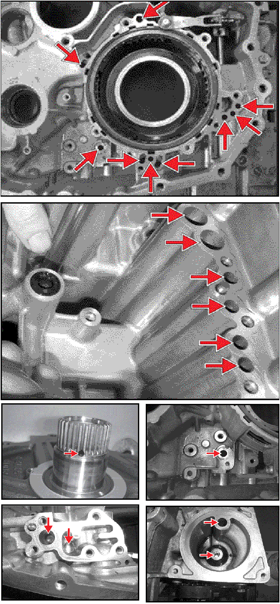
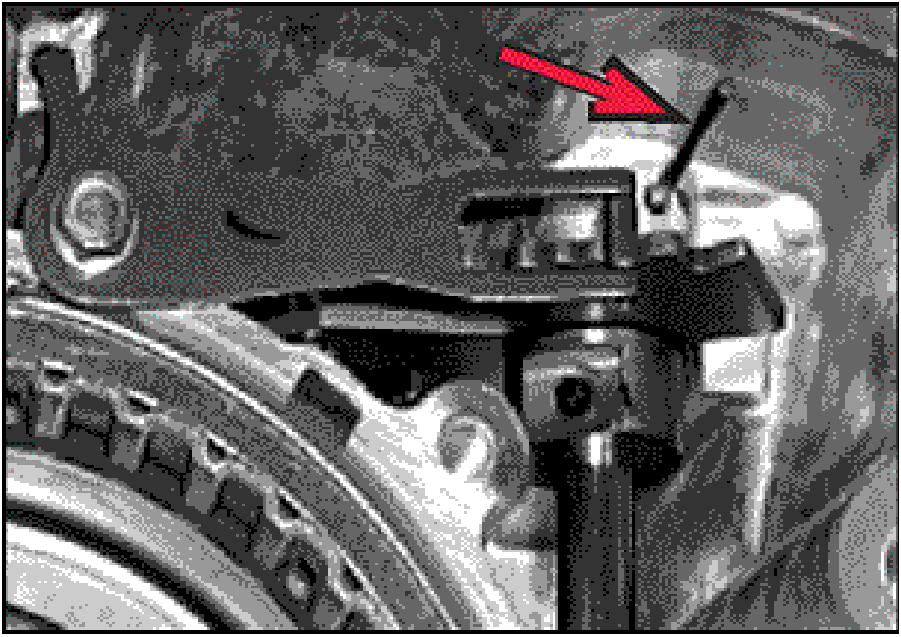
- Remove the five LONG converter housing mounting
bolts identified by the dimple located in the center of
the hex head. as indicated by the arrows.
|
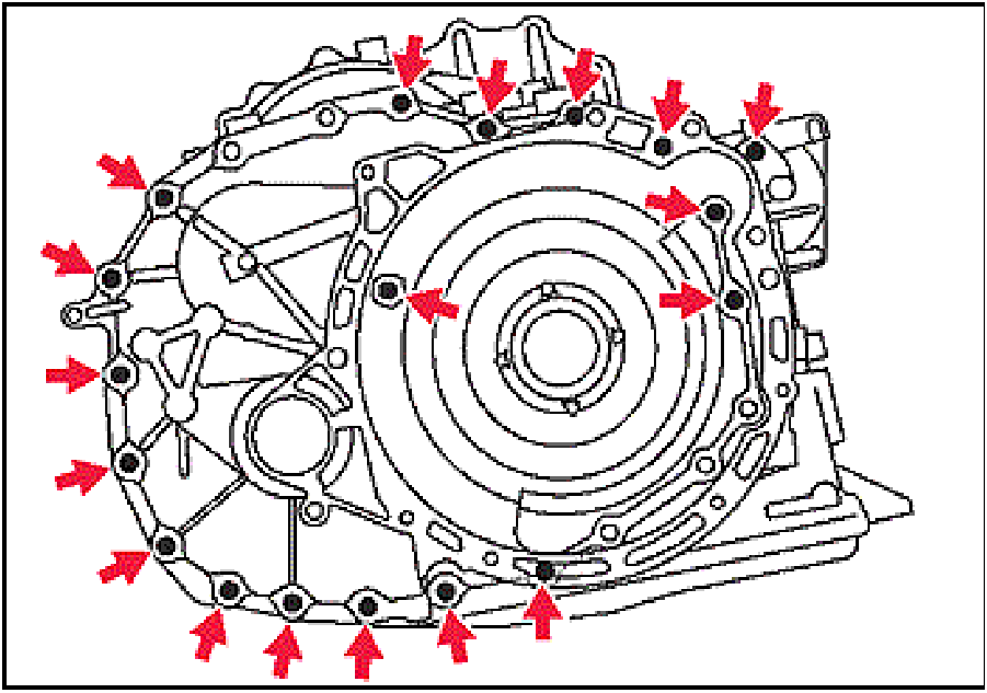 |
- Remove the eighteen SHORT converter housing
mounting bolts.
Use a deadblow mallet to carefully remove the
converter housing from the transaxle case.
|
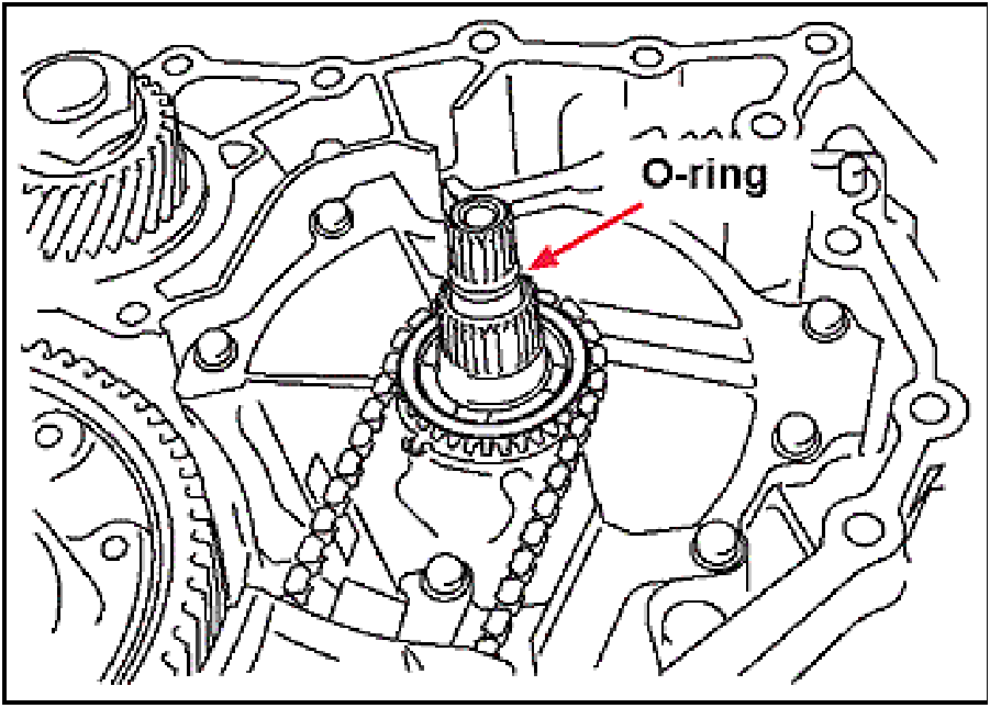 |
- Remove and discard the input shaft o-ring.
|
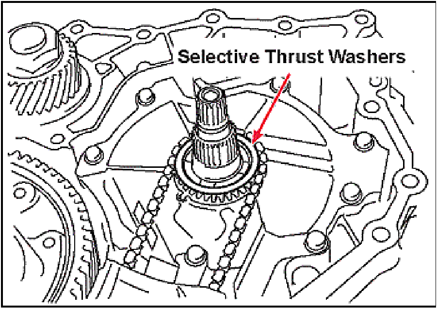 |
- Remove the two selective thrust washers from the oil
pump drive sprocket.
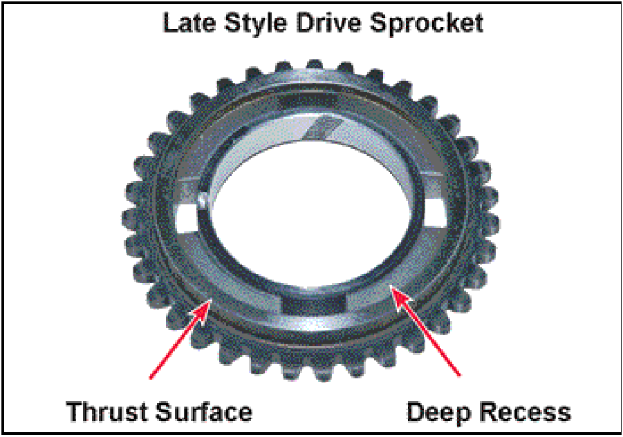
NOTE: The drive sprocket used with transaxles
starting with serial # Y08808317 was redesigned
which eliminated the need for selective shims.
|
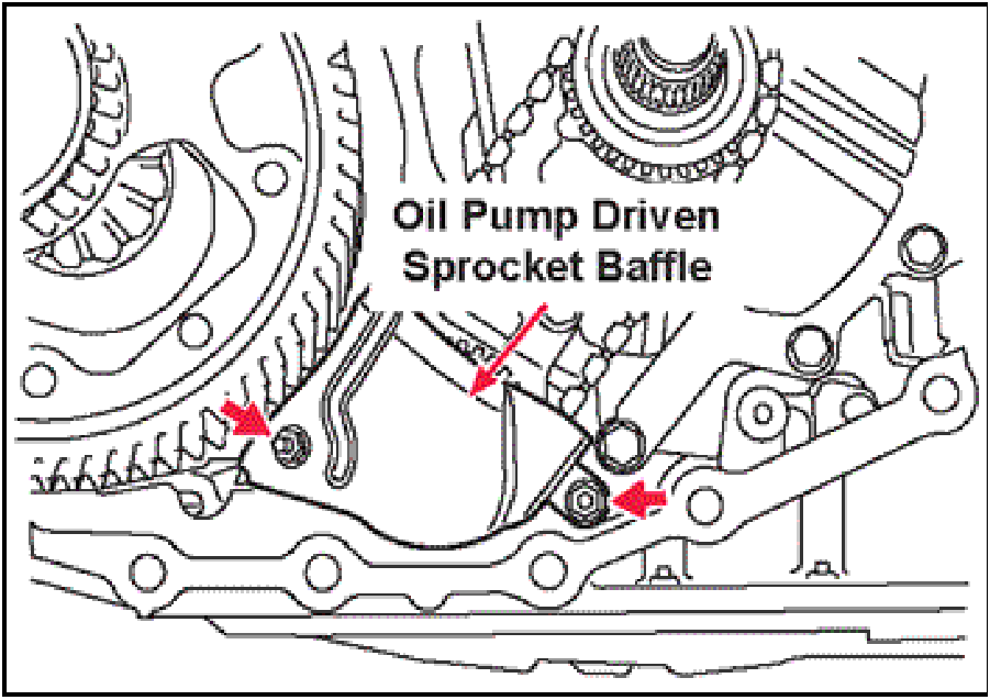 |
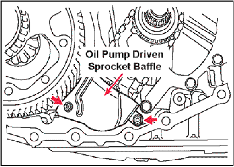
- Remove the two oil pump driven sprocket baffle
mounting nuts, then remove the baffle.
|
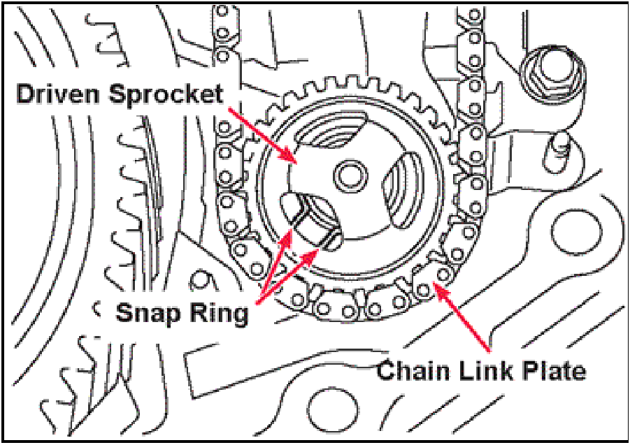 |
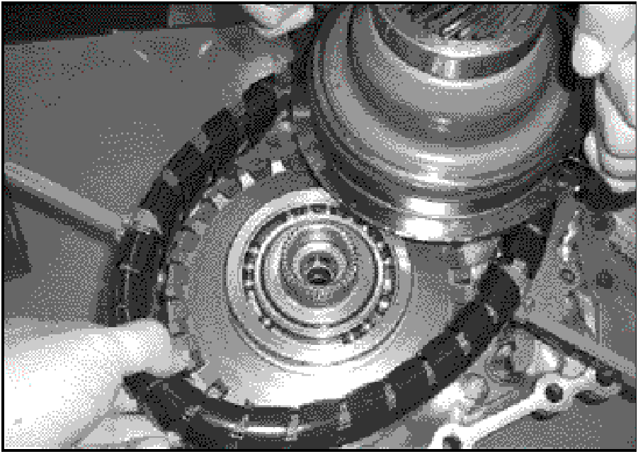
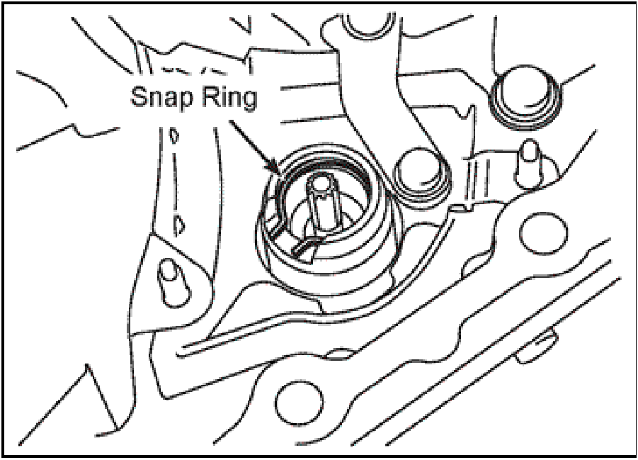
- Rotate the oil pump driven sprocket until one of the
three cutouts in the driven sprocket lines up with the
opening in the snap ring.
|
 |
- Using a pair of external snap ring pliers, expand the
snap ring and slide both sprockets and the chain
upward to remove them from the transaxle.
Discard the chain
|
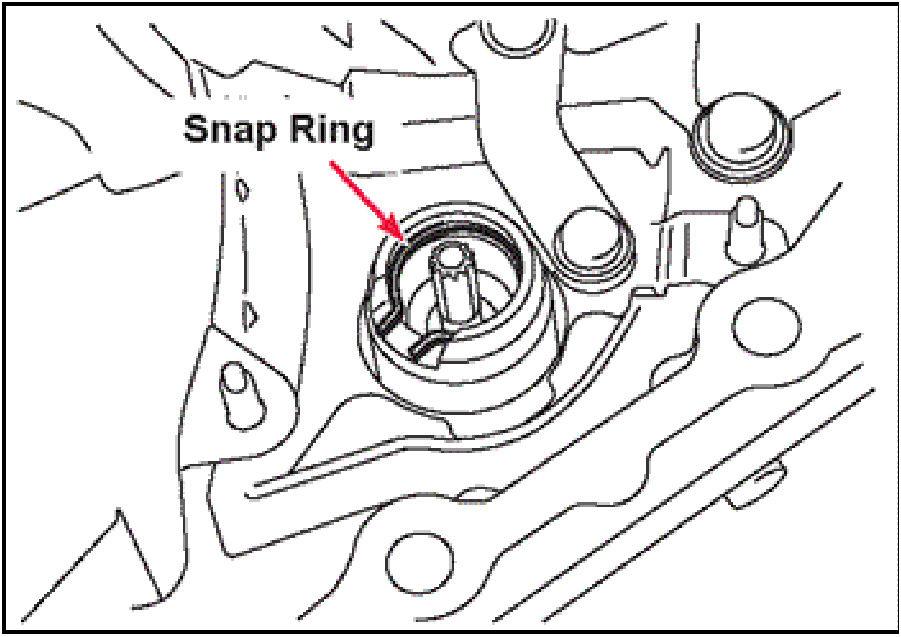 |
- Remove the snap ring from the oil pump housing
bearing bore.
Discard the snap ring.
|
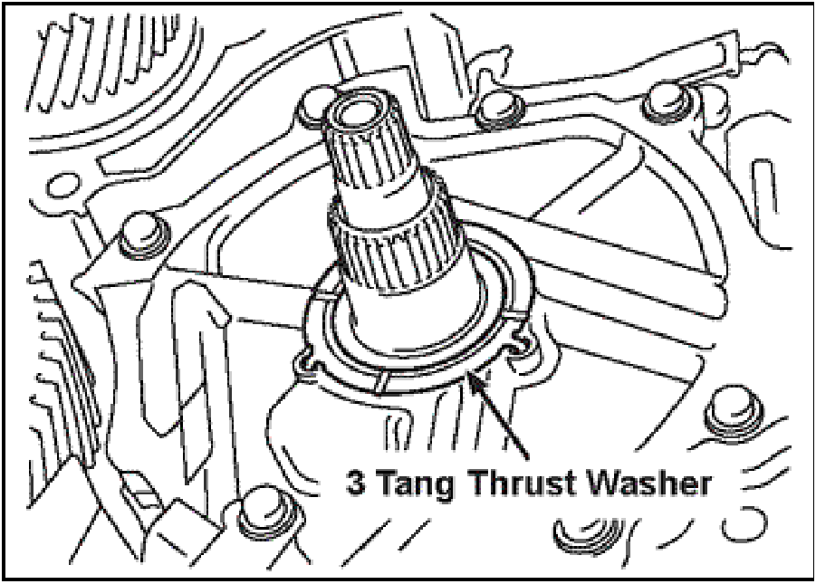 |
- Remove the three tang thrust washer from the pump
cover (stator support).
|
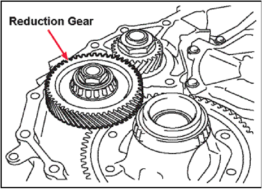 |
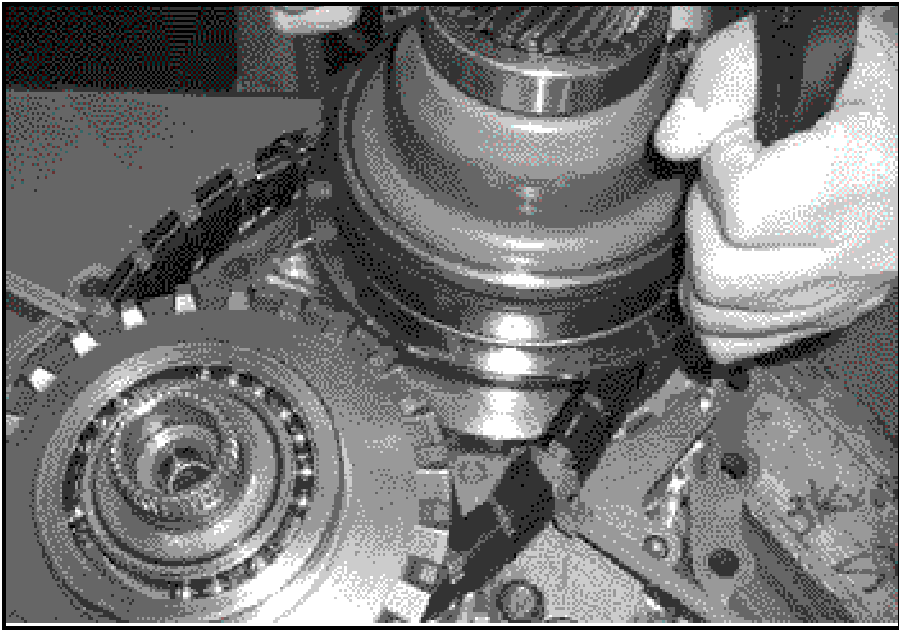
- Remove the reduction gear assembly.
Carefully inspect the bearings for roughness or
damage. Replace as necessary.
|
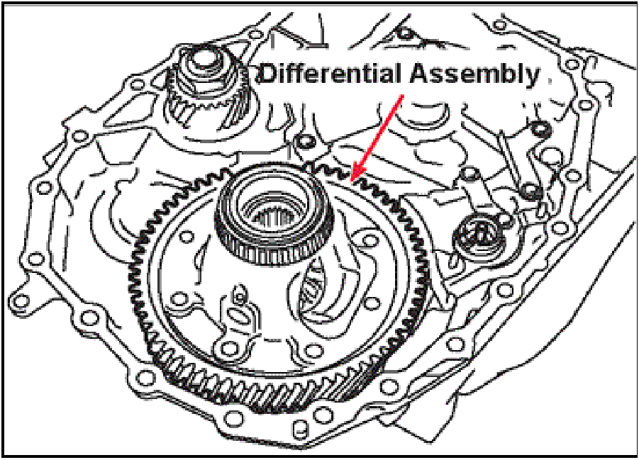 |
- Remove the differential assembly.
Carefully inspect the bearings for roughness or
damage. Replace as necessary.
|
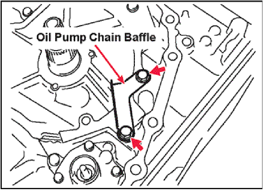 |
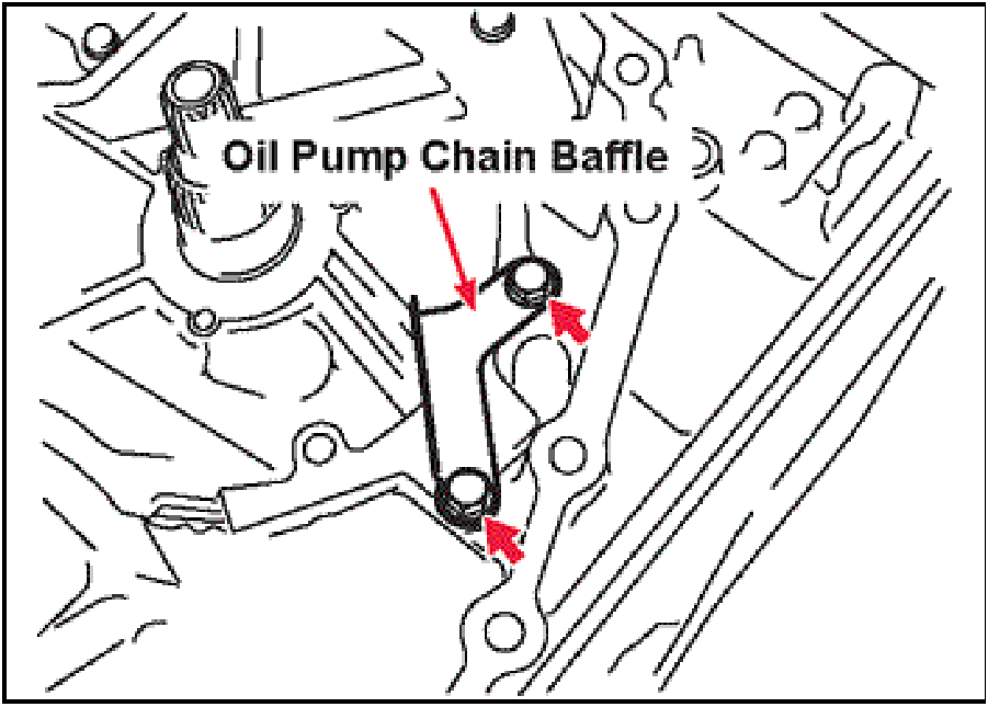
- Remove the two oil pump chain baffle mounting bolts,
then remove the oil pump chain baffle.
|
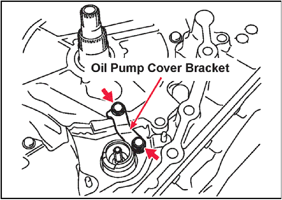 |
- Remove the two oil pump to pump cover (stator
support) bracket mounting bolts, then remove the
bracket.
|
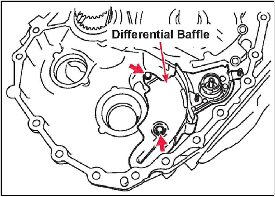 |
- Remove the two differential baffle mounting bolts, then
remove the baffle.
|
 |
- Remove the remaining five oil pump cover (stator
support) mounting bolts, then remove the oil pump
cover (Stator support) from the case.
|
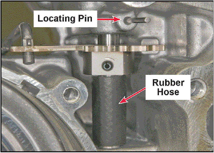 |
- Cut a small piece of fuel hose and install it onto the
manual control shaft is shown.
Using your fingers or a stick magnet remove the
manual control shaft locating pin from the case.
Failure to install the fuel hose will cause damage to the
non-serviceable manual shaft seal.
|
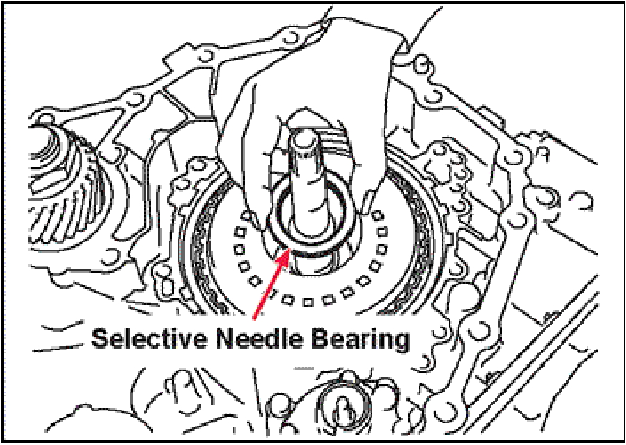 |
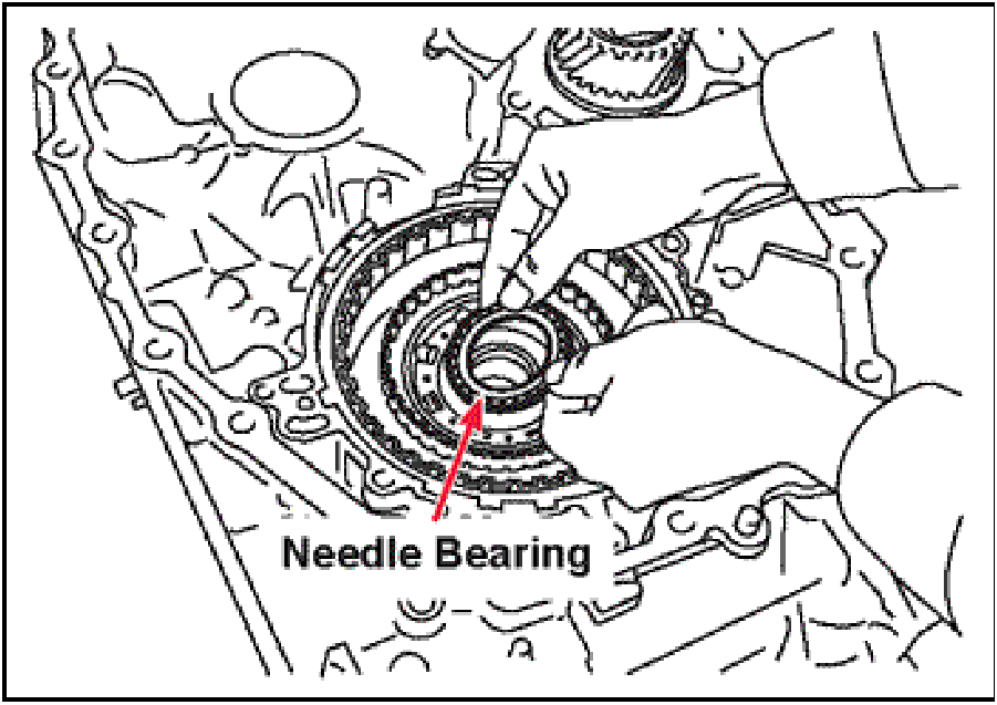
- Remove the selective needle bearing assembly from
the forward clutch drum.
NOTE: The selective needle bearing assembly may
have come out with the oil pump cover (stator support).
|
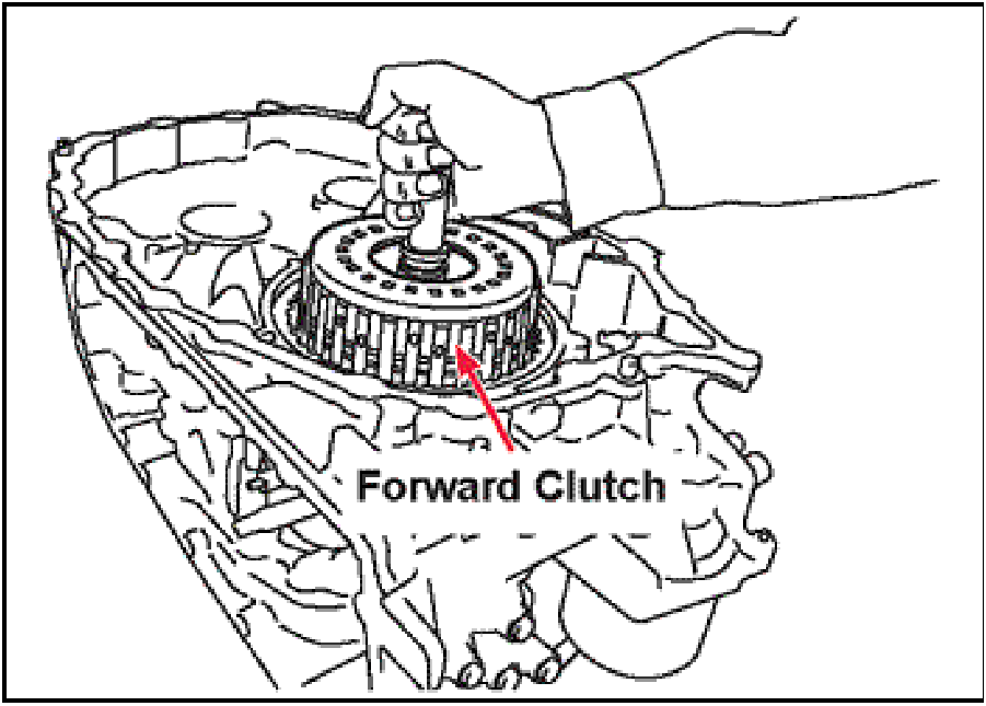 |
- Remove the forward clutch drum assembly from the
transaxle case
|
 |
- Remove the needle bearing assembly from the sun
gear.
NOTE: The needle bearing may have come out with
the forward clutch drum.
|
 |
- Remove the sun gear.
|
 |
- Remove the planet carrier (reverse brake clutch hub)
assembly from the transaxle case.
|
 |
- Remove the pan
Discard the pan gasket
|
 |
- Remove the strainer and 0-ring.
Discard both the strainer and 0-ring.
|
 |
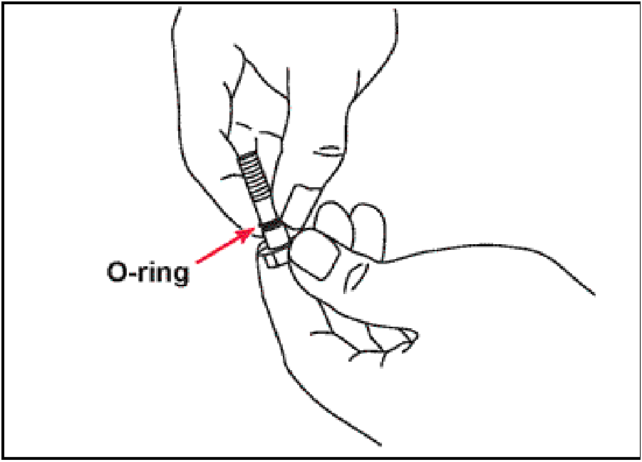
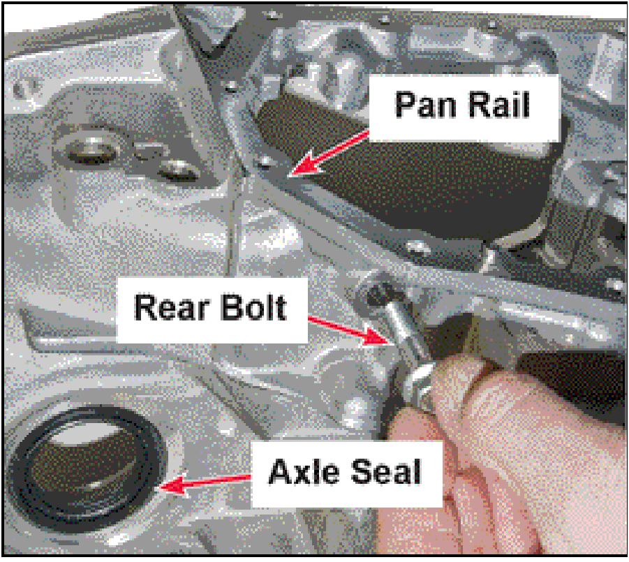
- Remove the one oil pump mounting bolt from the rear
of the transaxle case
Remove and discard the o-ring.
|
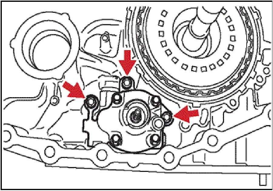 |
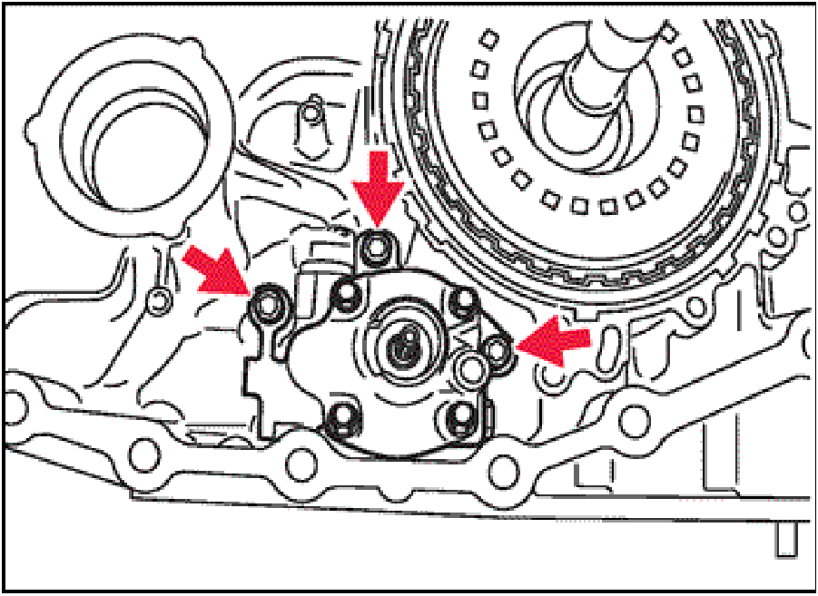
- Remove the three allen head oil pump mounting bolts.
Remove the oil pump from the transaxle.
DO NOT remove the four hex head bolts from the
oil pump assembly, this will cause damage to the
oil pump.
|
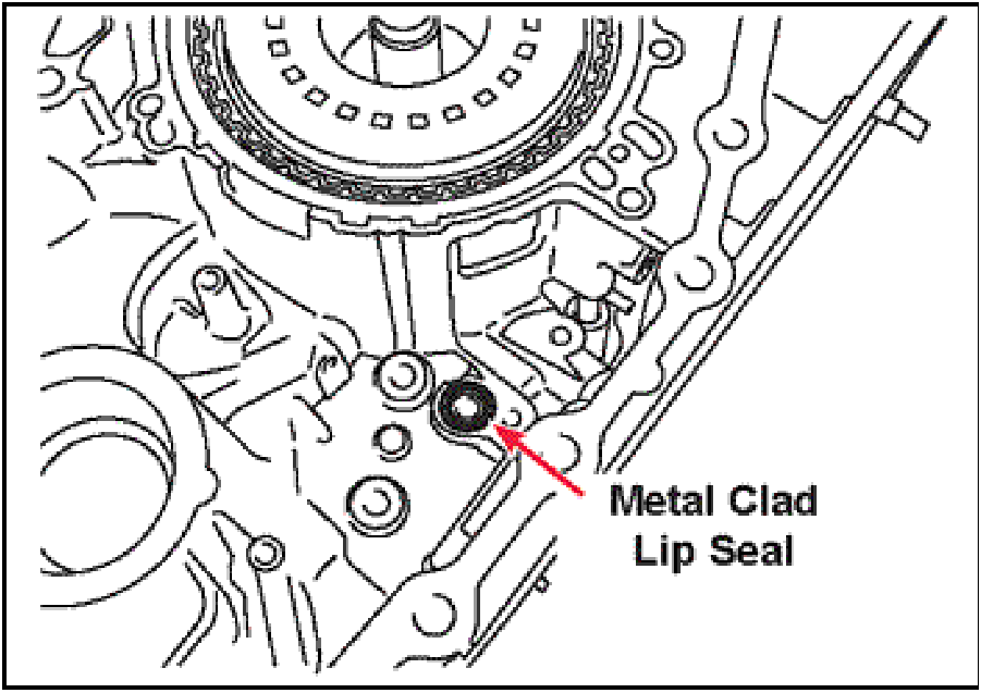 |
- Remove and discard the metal clad lip seal from the
transaxle case.
|
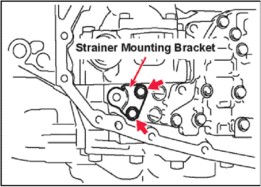 |
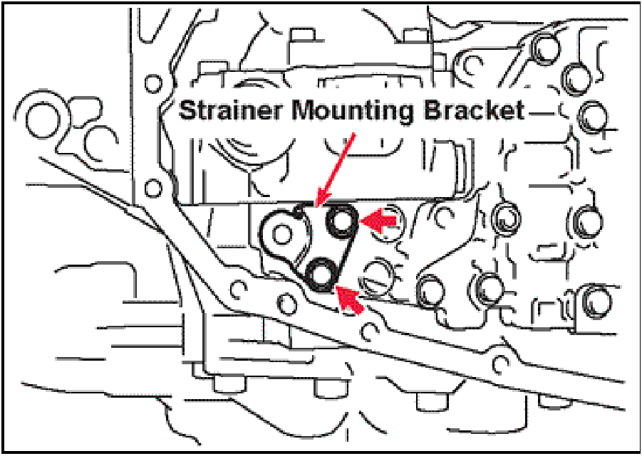
- Remove the oil strainer mounting bracket from the
valve body.
|
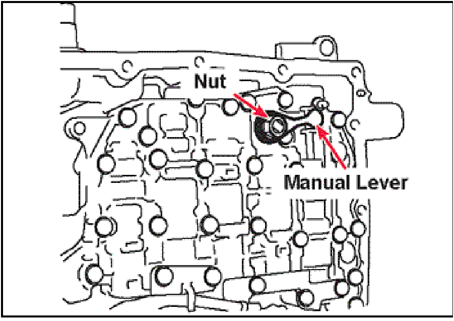 |
- Remove the nut and lock washer from the manual
control shaft.
Remove the manual valve control lever.
|
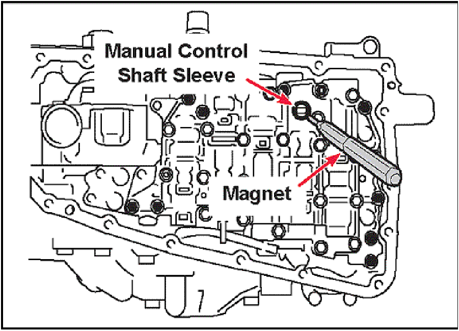 |
- Using a magnet, remove the manual control shaft
sleeve from the valve body.
|
 |
- Insert a 0.120” (3 mm) diameter, 5.0” (126 mm) long pin
into the retaining pin hole in the valve body.
NOTE: Cut a 5.0 in. piece out of an old coat hanger
or use special tool MB995015-01.
|
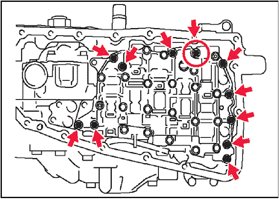 |
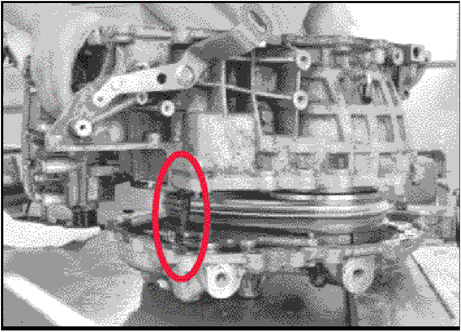
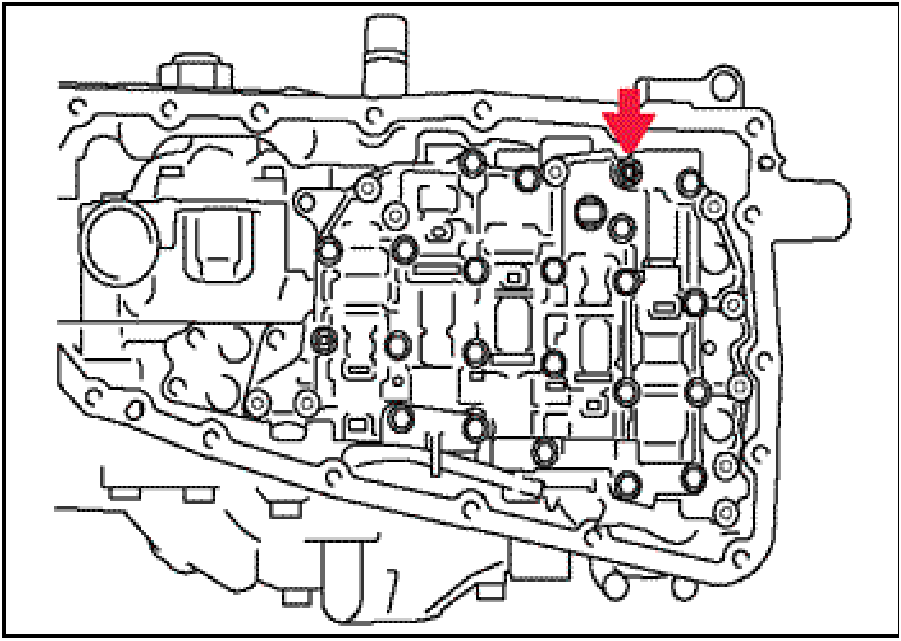
- Remove the one short valve body bolt indicated by the
circle, then remove the remaining ten long valve body
mounting bolts.
|
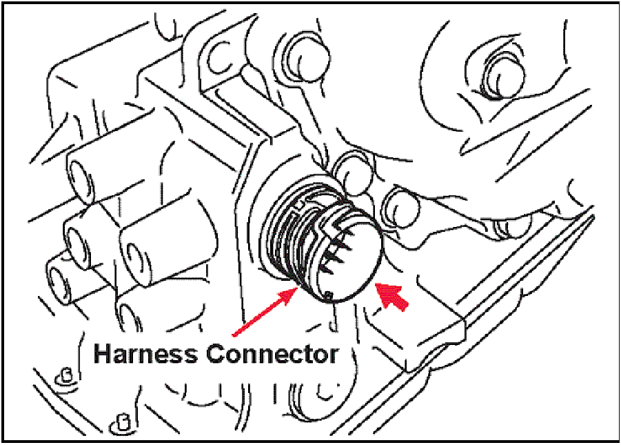 |
- Remove the valve body by carefully sliding it back off
of the manual control shaft while pushing the harness
connector into the transaxle case.
|
 |
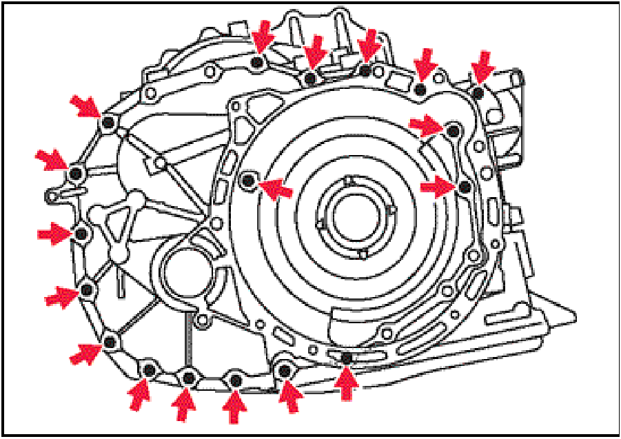
SIDE COVER DISASSEMBLY
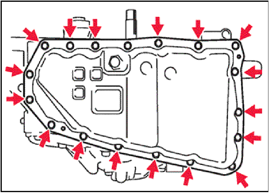
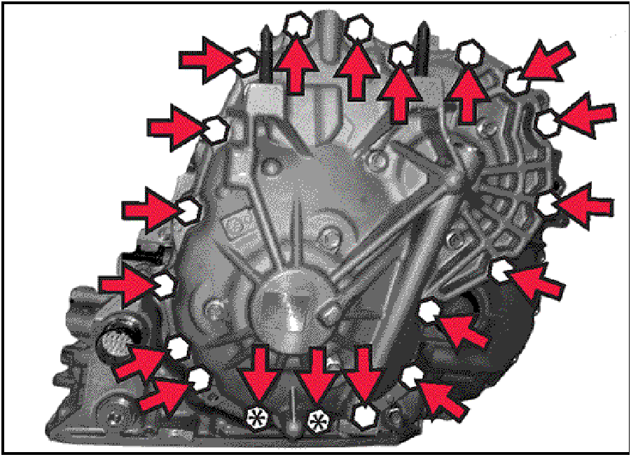
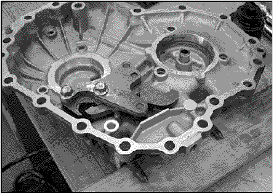
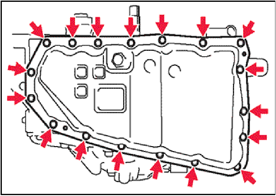
- Remove 19 case bolts as shown by the arrows.
Note the 2 bolts marked with * in the picture are 5mm
longer than the remaining 17 bolts.
17 bolts - 30mm long
2 bolts - 35mm long
|
 |
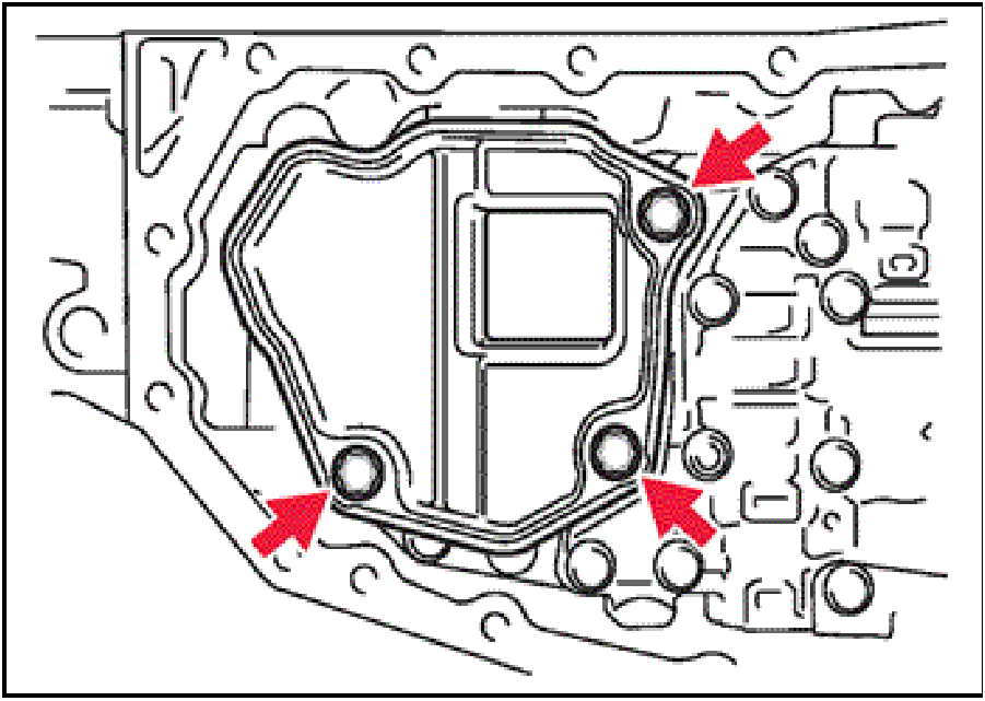
- Remove the 6 bearing retainer bolts from the side
cover as indicated by the arrows.
Rotate the transaxle onto the side cover (converter
housing pointing up) and level the assembly with wood
blocks.
|
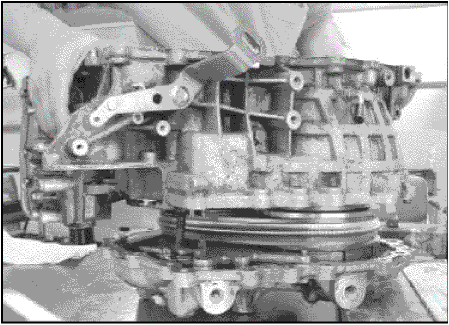 |
- Separate the transaxle case from the side cover to
expose the pulley assemblies.
|
 |
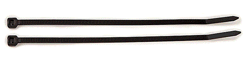
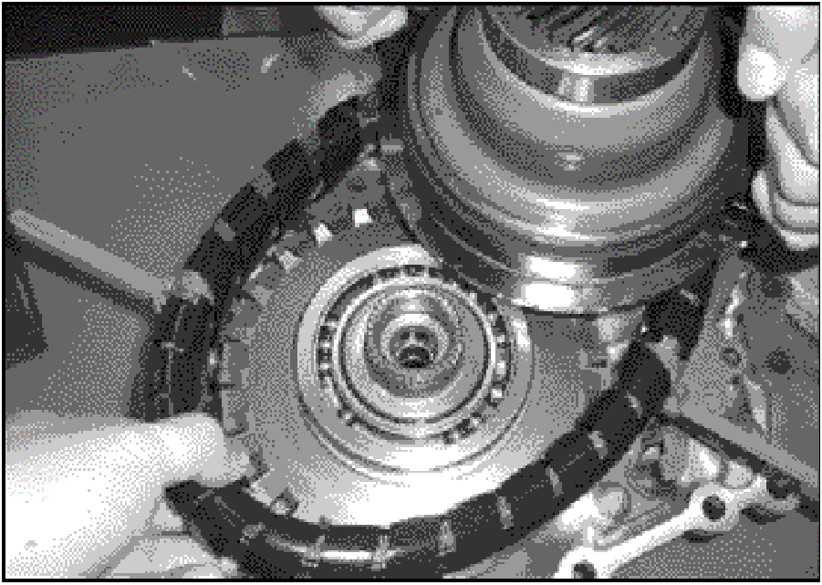
- Keep the drive belt from separating during further
disassembly by securely attaching two tie-wraps
around the belt at the locations shown by the arrows.
|
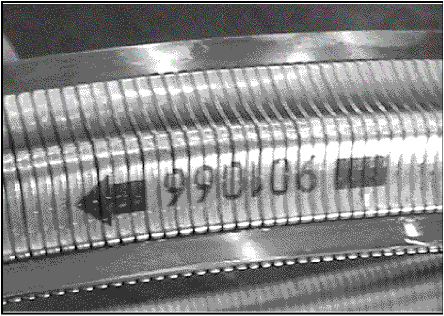 |
- Note of the direction arrow marked on the belt.
On reassembly, the belt MUST be reinstalled with the
arrow pointing in the same direction as it was removed
|
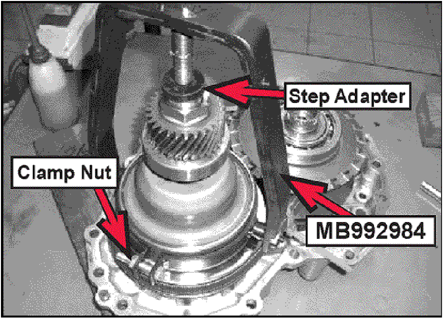 |
- Place a 1.375” step adapter on the shaft.
NOTE: This tool compresses the pulley's internal
spring, expanding the pulley width allowing belt to
be removed.
|
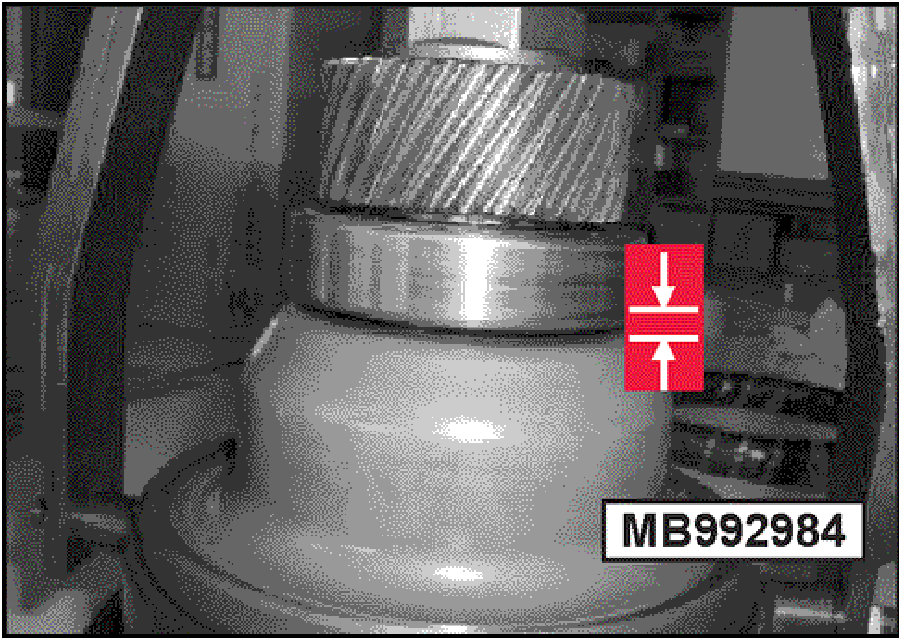 |
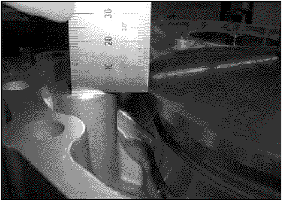
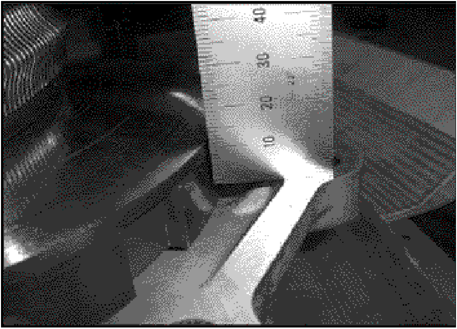
- Turn the forcing screw clockwise. STOP turning when
3mm is measured at the location shown.
Overtightening the forcing screw will damage the
secondary return spring.
|
 |
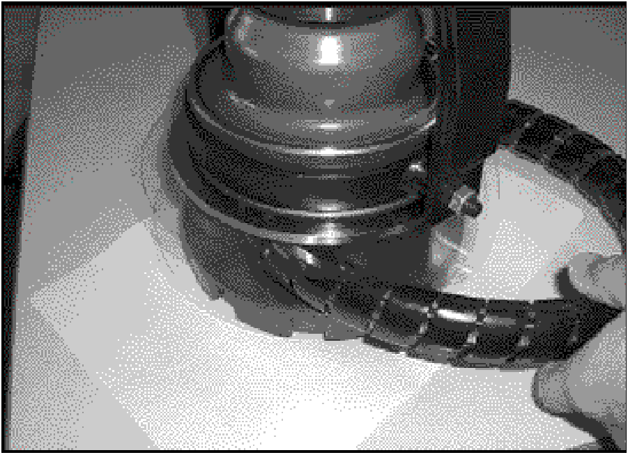
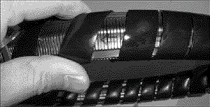
- To prevent damaging the belt during further steps,
wind approximately 28” (711mm) of convolute tubing
around its entire length.
|
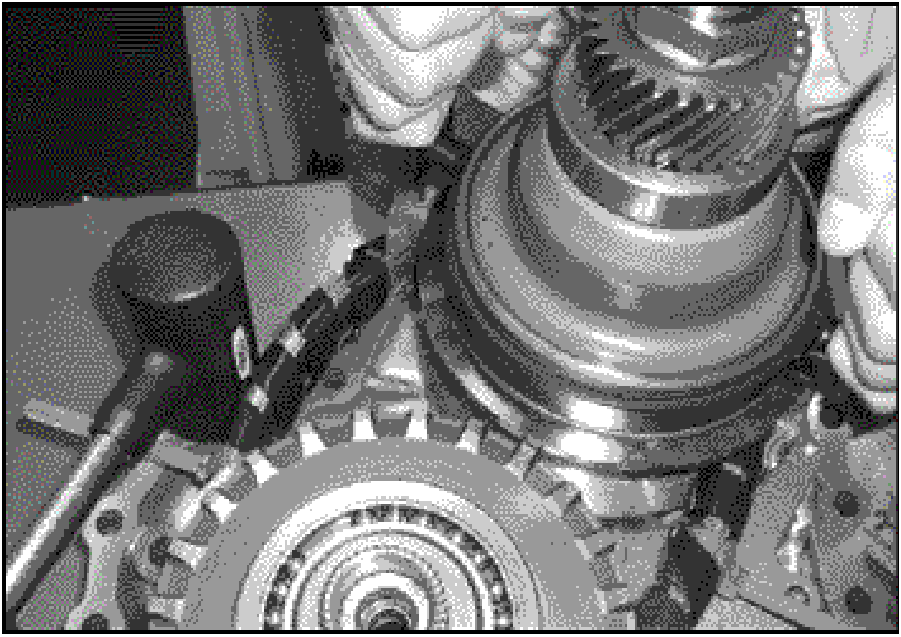 |
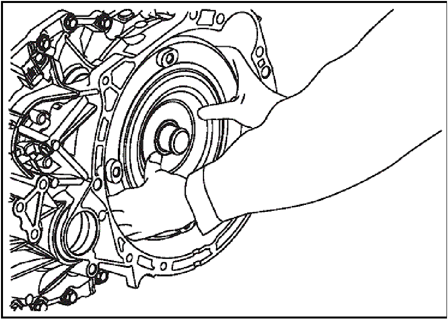
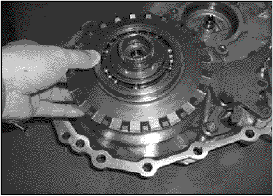
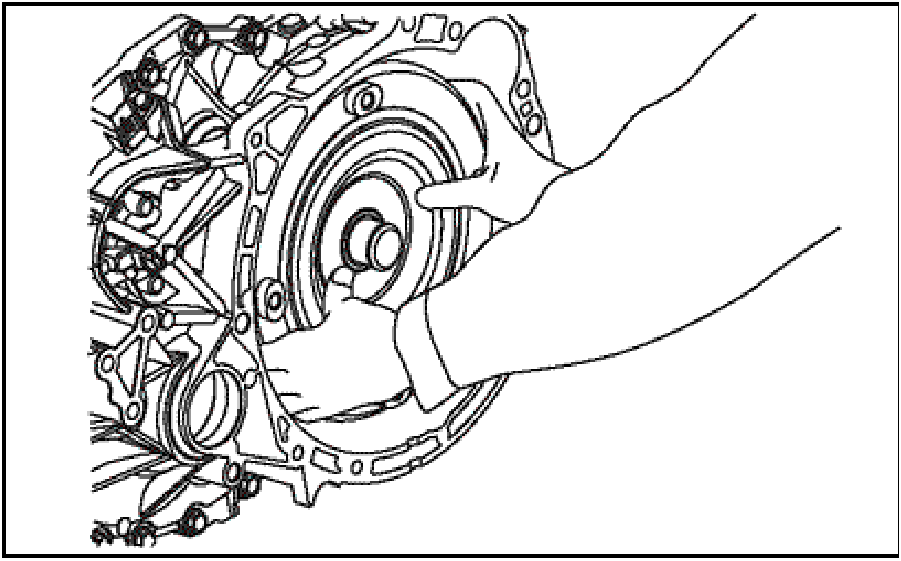
- Firmly grasp the compressor with both hands and lift
the secondary pulley assembly from the side cover.
|
 |
- Once the bearing is free from the side cover, move the
secondary pulley assembly toward the primary pulley.
The added slack in the belt will enable another
technician to slide the belt up and over the primary
pulley as shown here.
- Once the secondary pulley is removed, lift the primary
pulley from the side cover.
|
 |
CLEANING
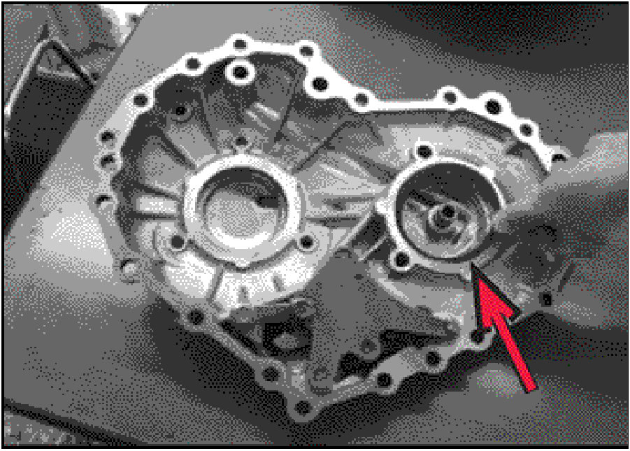
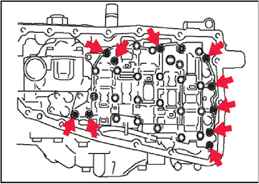
- While wearing eye protection, use a non-chlorinated
aerosol cleaner to flush each fluid passage indicated
by the arrows.
Immediately follow with compressed air to remove any
debris and cleaner residue.
|
 |
- Remove all residual liquid gasket sealer from these
mating surfaces:
- Converter Housing to Transaxle Case
- Transaxle Case to Side Cover
|
 |
- Thoroughly clean the transaxle pan and magnets.
|
 |
CASE SEALS and O-RINGS
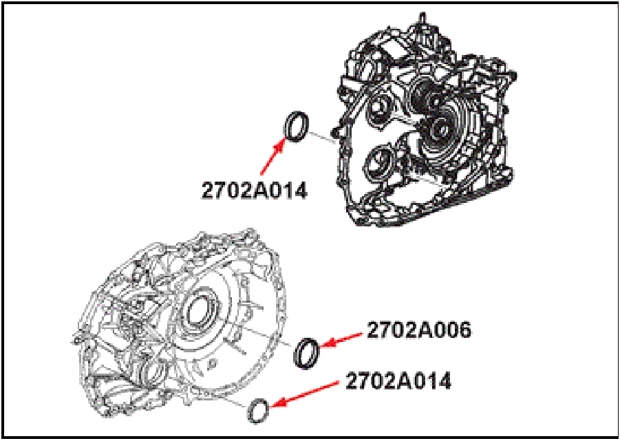
- Before proceeding further, replace the converter
housing seal and axle shaft seals. If necessary,
consult service manual Group 23B for procedures and
special tools.
Converter Housing Seal: 2702A006
Axle Seals: 2702A014
|
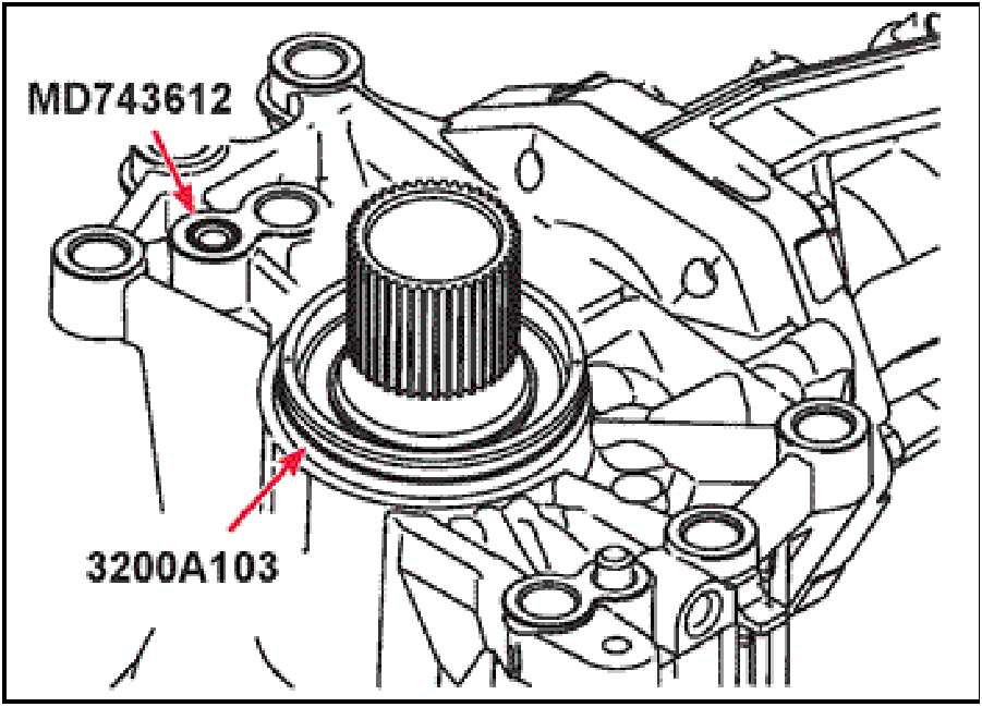 |
- If the vehicle is equipped with AWD, replace the
transfer case o-rings as shown here
Apply petroleum jelly to the recess in the case where
the small o-ring sits, then install the new o-ring
(MD743612) into the recess.
Install the new large o-ring (3200A103) into the
groove in the transfer case, then apply petroleum jelly
to the o-ring.
|
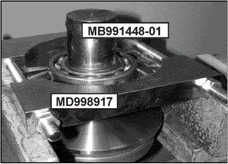 |
BEARING REPLACEMENT
- Press the primary pulley’s front bearing from the shaft
using special tools MD998917 and MB991448-01 as
shown. Discard the bearing.
NOTE: Ensure the bearing splitter's jaws are fully
seated under the bearing outer race. Do not use the
bearing’s C-ring groove to perform this step.
|
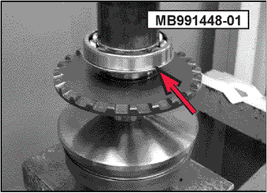 |
- Ensure all surfaces are free of debris. Use special tool
MB991448-01 to press the new bearing (2950A049)
onto the primary pulley shaft.
Ensure the bearing's C-ring groove faces the pulley
flange as indicated by the arrow.
|
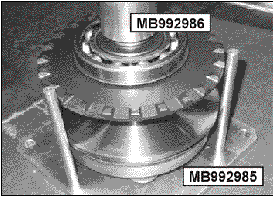 |
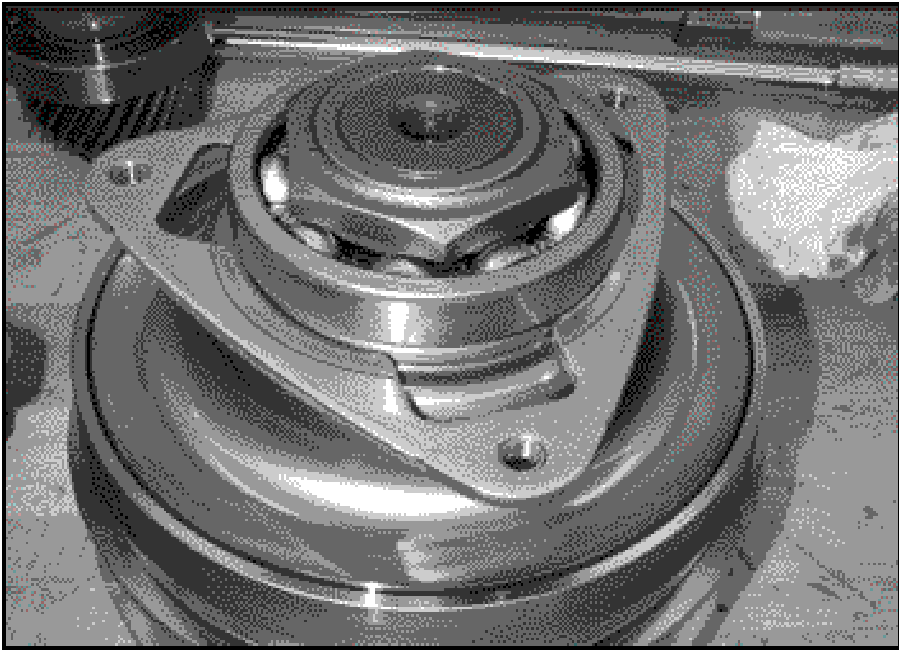
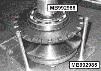
- Clamp the holding fixture (MB992985) to the
workbench. Place the primary pulley assembly (lock
nut down) into the 50mm hexagonal opening in the
fixture as shown.
Place the primary pulley holder (MB992986) onto the
splines. Using a breaker bar, loosen the lock nut.
Turn the assembly over, remove the lock nut and
discard it.
|
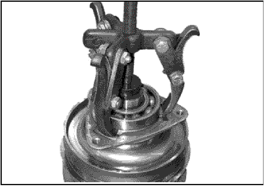 |
- Use a 3-jaw puller to remove the primary pulley's rear
bearing. Discard the bearing and bearing retainer
|
 |
- Clean all surfaces of any debris. Position the new
bearing retainer (2771A001) as shown here.
Do not install the retainer upside down.
|
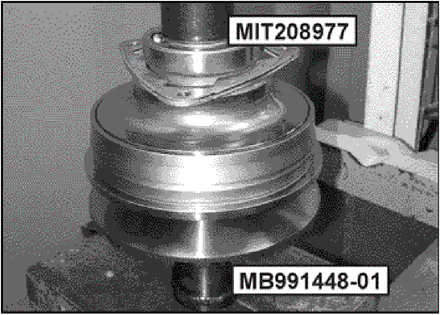 |
- Set a new primary pulley bearing (2950A047) in place.
Using special tool MB991448-01 to support the
assembly on the press table, seat the new bearing
onto the primary pulley shaft with MIT-208977.
|
 |
- Thread the new 50mm lock nut (2771A004) in place.
|
 |
- Insert the assembly into the holding fixture
(MB992985).
Use the primary pulley holder (splined socket)
(MB992986) to tighten the 50mm lock nut to 130Nm
(96 ft-lbs.).
|
 |
- Position the secondary pulley assembly (lock nut
down) in the holding fixture (MB992985) as shown.
Use a 40mm socket and breaker bar on the staked nut
to loosen the 50mm lock nut being held by the fixture.
|
 |
- Before attaching a flange puller, place the press button
(MB995049-01) onto the shaft.
Use three 8mm x 1.25mm screws to attach the puller
to the bearing retainer. Turn the forcing screw against
the press button to remove the secondary pulley's front
bearing.
Discard the bearing and bearing retainer.
Retainer may be deformed during this step.
|
 |
- Position the new bearing retainer (2771A002) and new
bearing (2950A048) onto the secondary shaft as
shown here.
Do not install the bering retainer upside down.
|
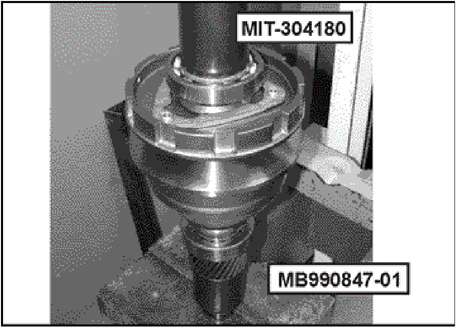 |
- Support the output gear on the press table with special
tool MB990847-01.
Use special tool MIT-304180 to press the bearing onto
the secondary pulley shaft.
|
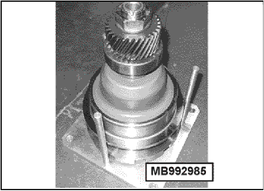 |
- Thread a new 50mm lock nut (2771A003) onto the
shaft and return the secondary pulley assembly to the
holding fixture (MB992985) as shown.
Use a 40mm socket and torque wrench on the staked
nut to tighten the new lock nut (held by the holding
fixture) to 310Nm
(228 ft-lbs.).
|
 |
- Install a new sealing ring (2931A005) as shown here.
NOTE: There may be 2 sealing rings depending
upon design. If so, replace both.
|
 |
- To make component installation easier, level the side
cover with wood block(s).
|
 |
- Install the primary pulley into the side cover.
|
 |
- With slight downward pressure, shake the primary
pulley assembly until the bearing is fully seated in the
side cover.
Check the installed position by measuring the
dimension as shown.
The pulley flange should protrude above the side
cover mating surface by 1.5mm to 2.0mm (0.059” to
0.078”).
|
 |
- Attach the compressor (MB992984) over secondary
pulley as shown in Step 39. Turn the forcing screw
clockwise. STOP turning when 3mm (.118”) is
measured at the location shown.
Overtightening the forcing screw will damage the
secondary return spring.
|
 |
- Install the belt around the secondary pulley. Note the
directional arrow.
|
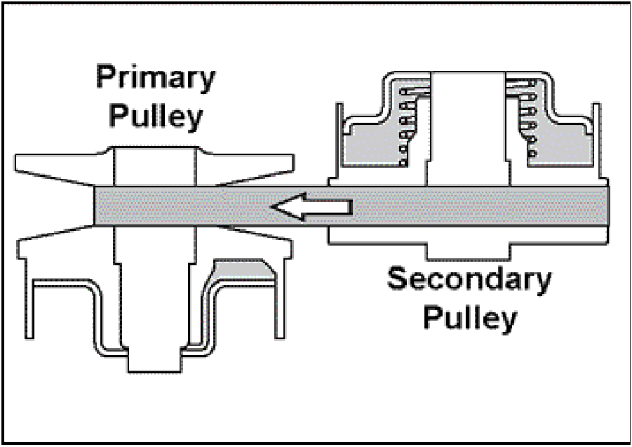 |
- Verify the arrow's direction matches the drawing
shown here.
|
 |
- Hold the compressor close to the primary pulley while
another technician slides the belt into the primary
pulley groove.
|
 |
- Once the belt is in position, install the secondary pulley
assembly into the side cover.
Like the primary pulley installation, shake the
assembly until the bearing is seated.
|
 |
- The pulley flange should stand 12mm (.472”) above
the side cover when the bearing is fully seated.
Once the secondary pulley assembly is fully seated,
remove the compressor (MB992985).
Remove the protective convolute tubing and tie-wraps
from the belt.
|
 |
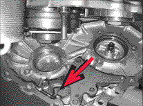
- Shift to PARK position. Align the park rod into position,
shown by the arrow, and lower the converter housing
onto the side cover.
|
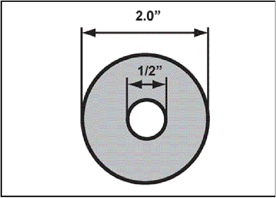 |
- To hold the secondary pulley assembly stationary in
the side cover as the transaxle is flipped over in step
83, use a 2” x 1/2 fender washer.
|
 |
- Insert fender washer into the space between the
output gear and the bearing.
Use flat washers underneath the fender washer to
level it.
Secure with a bolt, finger tight only.
|
 |
- Install two bolts to hold the transaxle case and side
cover together temporarily.
Turn the transaxle over and position on wood blocks
with the side cover facing up. Verify the output gear
clears the workbench.
Remove the two bolts and remove the side cover.
|
 |
- Install the primary pulley sensor. Note the spring
installation direction as shown by the arrow.
|
 |
- Install the manual shaft locating pin.
Remove the fuel hose installed in step 23
|
 |
- Install new o-ring (270A078) as shown.
|
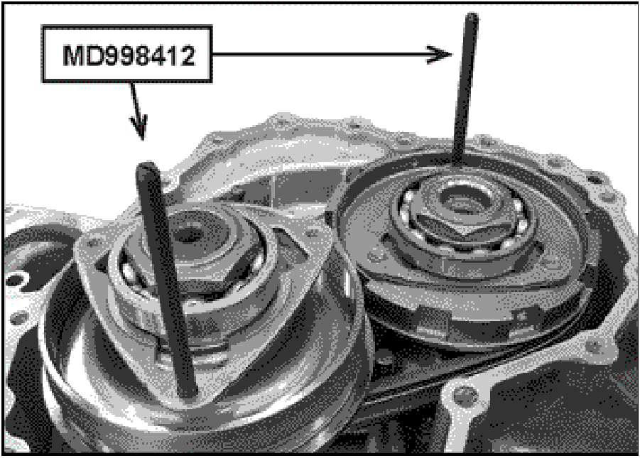 |
- To simplify aligning the bearing retainers with the side
cover bolt holes, loosely install guide pins (MD998412)
as shown.
NOTE: As the guide pin threads are different than
the retainer's threads, do not tighten the guide
pins.
|
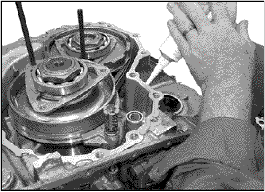 |
- Apply a 1.5mm (0.060”) bead of Loctite 509 (or
equivalent) to the mating surface of the side cover.
|
 |
- Install the secondary pulley side cover shim.
Because the side cover will be turned over in the next
step, use petroleum jelly to keep the shim in place.
|
 |
- Verify the shift linkage is in PARK. Lower the side cover
onto the transaxle case using the guide pins
(MD998412) to position the bearing retainers with their
bolt holes.
Take care to guide the park rod and speed sensor into
their locations in the side cover.
When properly aligned, seat the converter housing to
the side cover with a deadblow mallet.
|
 |
- Install the 19 case bolts and tighten to 45Nm (33
ft-lbs.) in the numbered sequence shown.
Make certain to install the two longer 35mm bolts at
locations 14 and 15.
|
 |
- Install new o-rings (2791A012) on the six bearing
retainer bolts.
|
 |
- After verifying the bearing retainers are properly
aligned, thread one bolt into each retainer to maintain
their positions.
Remove the guide pins.
Install the remaining bolts and tighten to 28Nm (21
ft-lbs.)
|
 |
REASSEMBLY PROCEDURES
- Turn the transaxle over on the workbench as shown,
supporting the side cover with blocks.
Installed in step 81, remove the fender washer from
under the output gear.
|
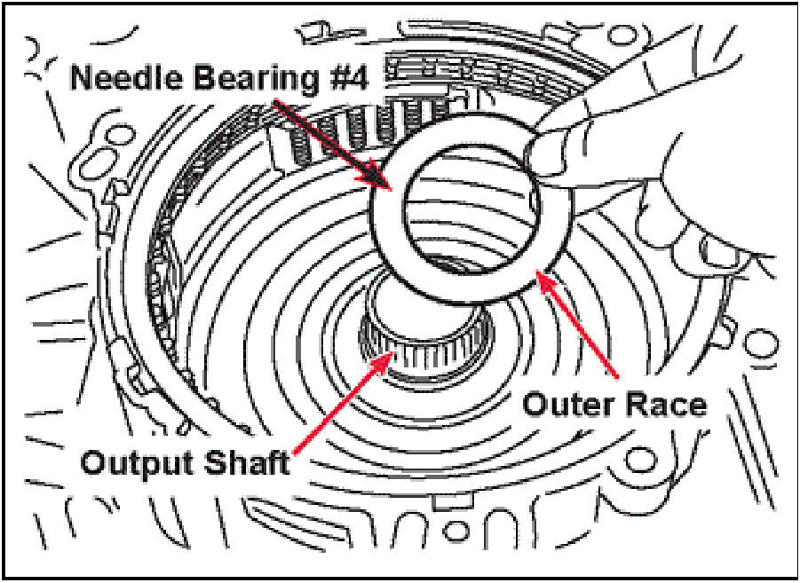 |
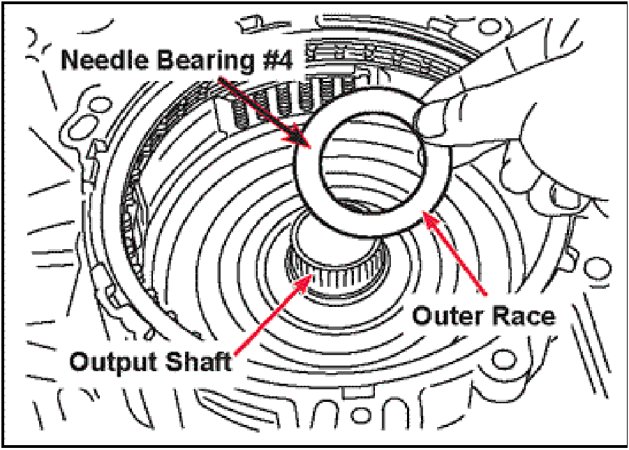
- Install the needle bearing assembly #4 located
between the output shaft and planet carrier with the
OUTER bearing race facing upward, over top of the
primary pulley drive splines.
|
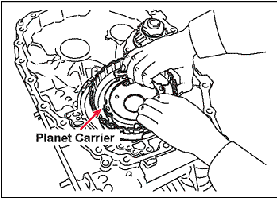 |
- Install the planet carrier into the transaxle case. Rotate
the planet carrier back and forth to make sure all clutch
friction discs are engaged with the hub. Continue until
the planet carrier is sitting down against the needle
thrust bearing.
|
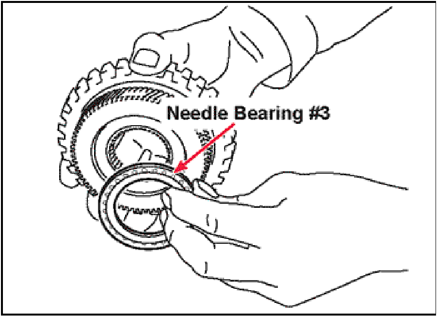 |
- Install the needle bearing assembly #3 located
between the planet carrier and the sun gear using
petroleum jelly to hold it onto the bottom side of the sun
gear with its OUTER race facing the sun gear.
|
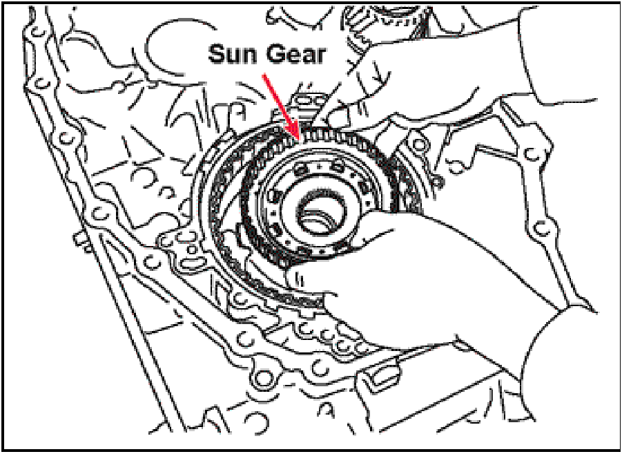 |
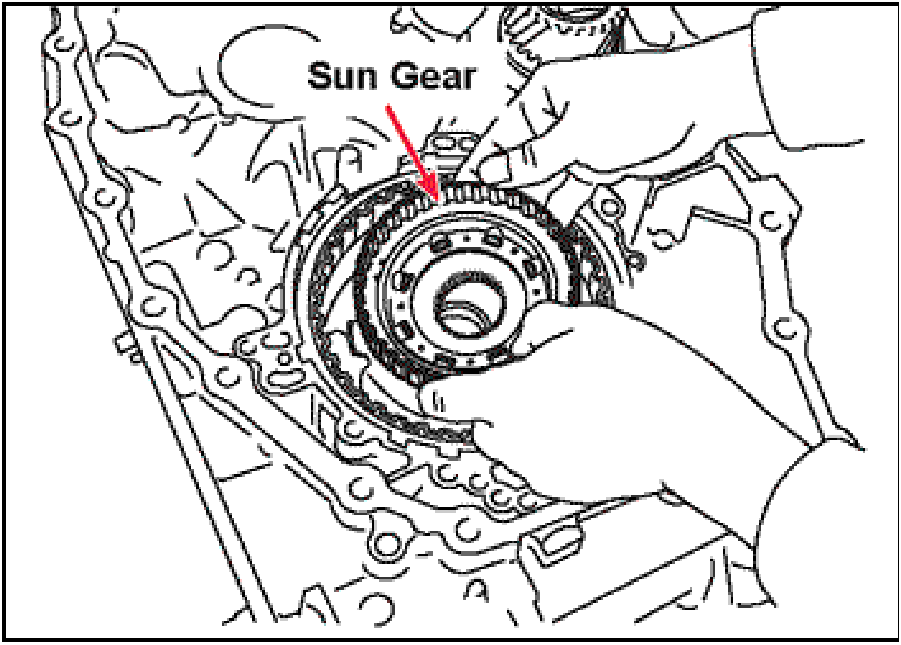
- Install the sun gear down into the planet carrier, rotate
it back and forth until it seats on top of the needle
bearing.
|
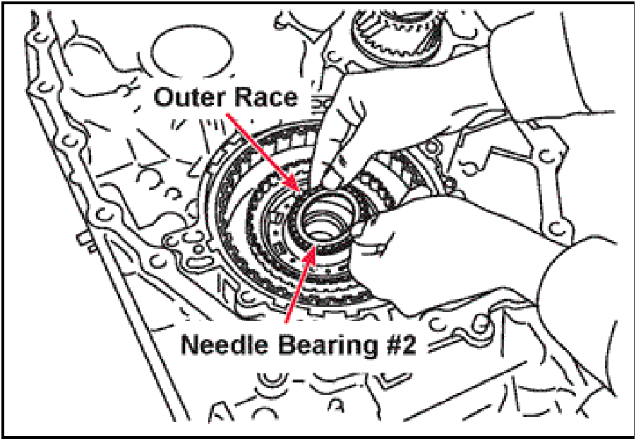 |
- Install the needle bearing assembly #2 between the
sun gear and forward clutch drum down into the top
side of the sun gear with the OUTER race facing
downward toward the sun gear.
|
 |
- Apply a coating of petroleum jelly to the sealing rings
and bushing surface on the back of the input shaft.
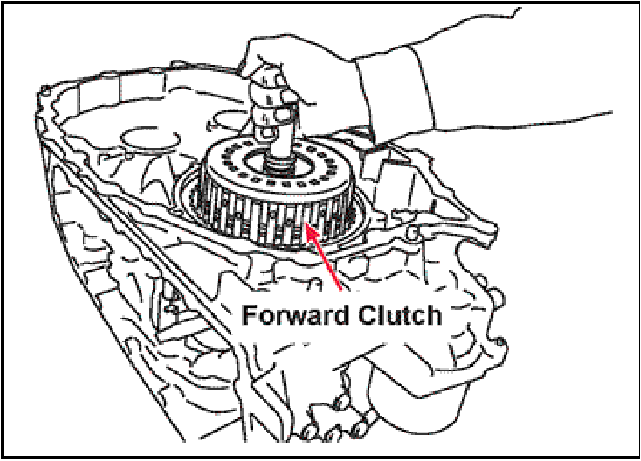
- Install the forward clutch assembly into the transaxle
case. Rotate the assembly back and forth until it is
drops down and is seated against the needle thrust
bearing.
|
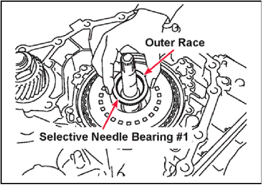 |
- Install the selective needle bearing assembly #1 down
into the forward clutch drum with the OUTER race
facing up.
|
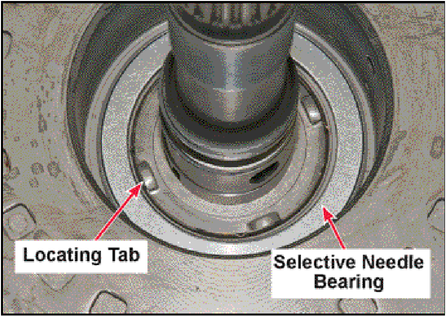 |
- Verify the bearing is not sitting on top of any of the
locating tabs on the forward clutch drum.
|
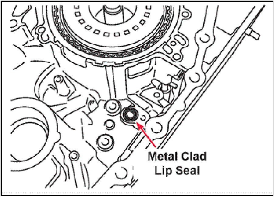 |
- Install a new oil pump metal clad lip seal (2791A014)
into the recess in the transaxle case using petroleum
jelly to hold it in position.
|
 |
- Lower the oil pump into the transaxle case.
Install the three allen head oil pump mounting bolts
finger tight only at this time.
3 — Long Bolts — 70 mm (2.75 in.)
|
 |
- Install a new o-ring (2791A012) onto the rear pump
mounting bolt. Then apply a coating of petroleum jelly
to the o-ring.
|
 |
- Install the rear oil pump mounting bolt into the back
side of the transaxle case finger tight only at this time.
- Tighten the three allen head oil pump mounting bolts
to 19Nm (14 ft-lbs.)
Tighten the rear mounting bolt to 28Nm (21 ft-lbs.)
|
 |
- Apply a coating of petroleum jelly to the new sealing
rings (2791A029) and bushing surfaces on the input
shaft and pump cover (stator support).
- Install the pump cover (stator support) and the five
mounting bolts into the locations indicated, finger tight
only at this time.
5 — Long Bolts — (30mm (1.18in.)
|
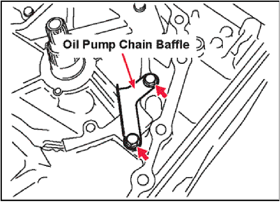 |
- Install the oil pump chain baffle in the location shown
using two mounting bolts.
Tighten all of the pump cover (stator support) and oil
pump chain baffle mounting bolts to 19Nm (14 ft-lbs.)
2 — Long Bolts — 30mm (1.18 in.)
|
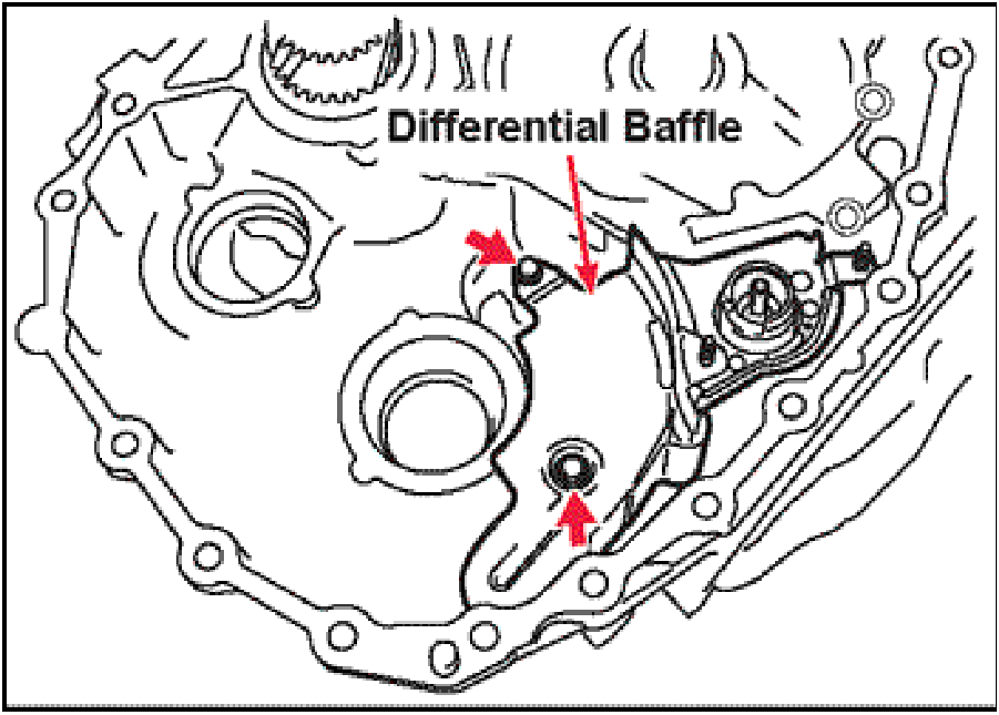 |
- Install the differential baffle plate and the two
mounting bolts.
Tighten the bolts to 5.8Nm (52 in-lbs.)
2 — Short Bolts — 16mm (.630 in.)
|
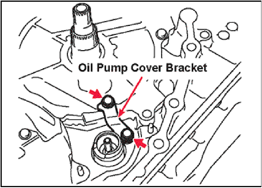 |
- Install the oil pump bracket with the two bracket
mounting bolts.
Tighten the bolts to 25Nm (19 ft-lbs.)
2 — Short Bolts — 16mm (.630 in.)
|
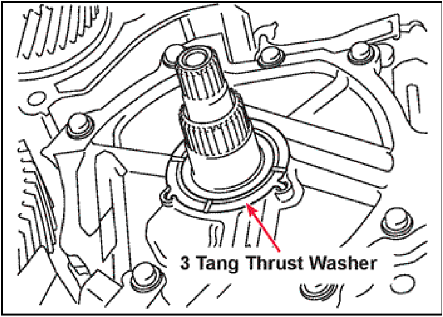 |
- Install the three tang Thrust Washer on the pump
cover (stator support) making sure the three tangs on
the thrust washer are in the three holes in the pump
cover (stator support).
|
 |
- Install the new driven sprocket ball bearing retaining
snap ring (2791A018) into the oil pump housing with
the opening in the snap ring aligned with the cutout in
the oil pump housing.
|
 |
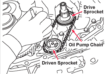
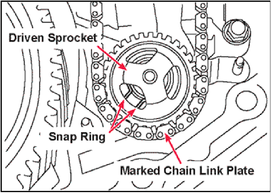
- Set the drive sprocket on the bench with the DEEP
RECESS FACING UP. Set the driven sprocket on the
bench with the ball bearing FACING DOWN.
Wrap the new chain (2791A024) around the sprockets
making sure the colored chain link is FACING UP.
|
 |
- With the sprockets and chain as positioned in step
115, slide the assembly down over the shafts.
|
 |
- Rotate the oil pump driven sprocket until one of the
three cutouts in the driven sprocket lines up with the
opening in the snap ring.
|
 |
- Using a pair of external snap ring pliers, expand the
snap ring, at the same time slide both the drive and
driven sprockets downward along with the chain until
the drive sprocket fully seats on the three tang thrust
washer.
- While expanding the snap ring carefully move the oil
pump driven sprocket up and down until the snap ring
seats in the groove in the outer race of the ball
bearing.
|
 |
- Install the oil pump driven sprocket baffle on the studs
in the transaxle case.
Install the two 10mm mounting nuts and tighten to
5.8Nm (52 in-lbs.).
|
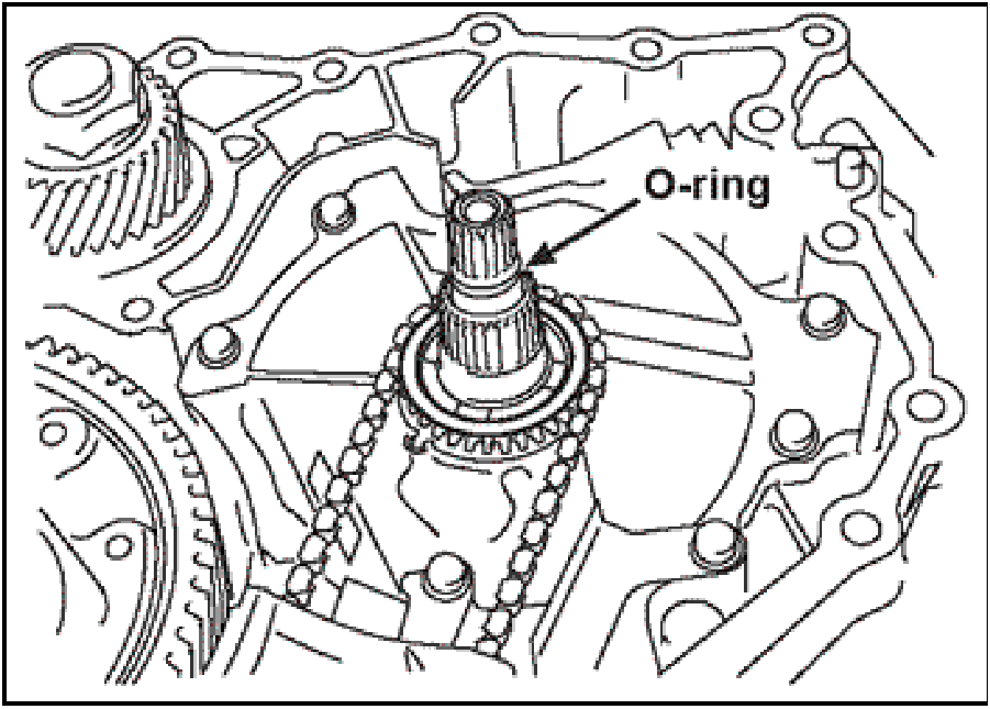 |
- Install a new o-ring (2761A009) into the groove on the
input shaft.
|
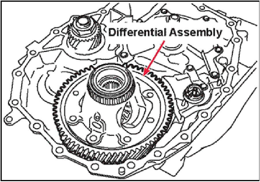 |
- Install the differential assembly into the transaxle
case.
If bearings were replaced, verify proper shim
thickness using Service Manual selection
procedures.
|
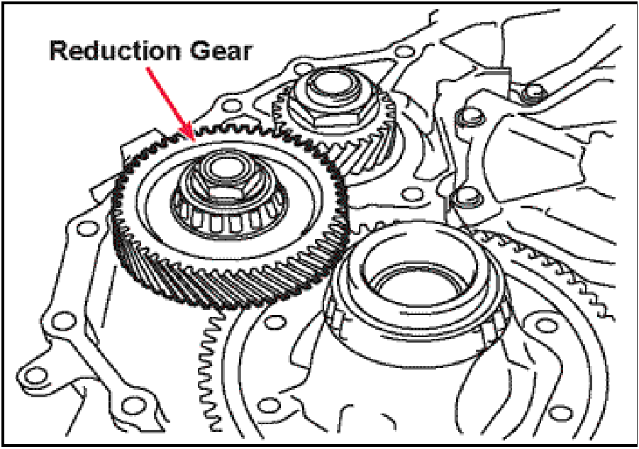 |
- Install the reduction gear assembly into the transaxle
case.
If bearings were replaced, verify proper shim
thickness using Service Manual selection
procedures.
|
 |
- Place a 1.5mm (0.60”) bead of Loctite 509 (or
equivalent) on the transaxle case mating surface.
Install the converter housing onto the transaxle case,
then install the five LONG converter housing
mounting bolts identified by the Dimple located in the
center of the hex head into the indicated locations.
5 — Long Bolts — (35mm (1.38in.)
|
 |
- Install eighteen SHORT converter housing mounting
bolts into the indicated locations.
Tighten all bolts to 45Nm (33 ft-lbs.)
18 — Short Bolts — (30mm (1.18in.)
|
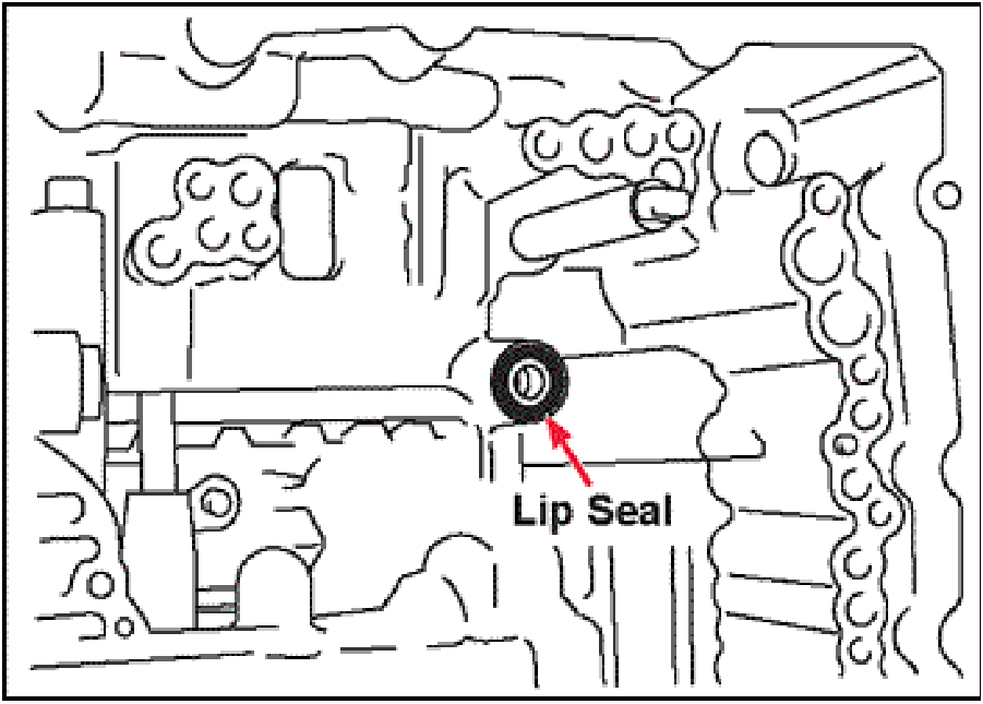 |
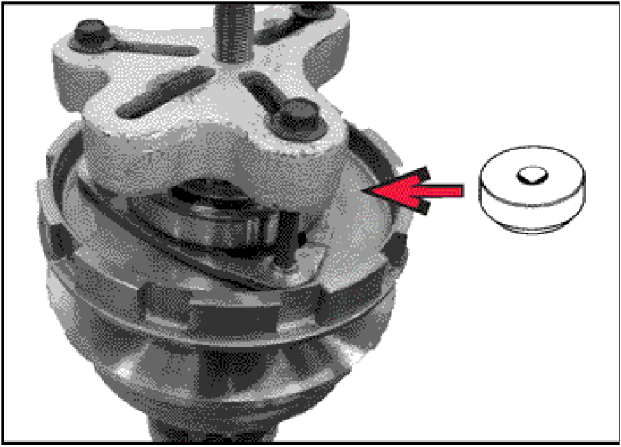
- Apply petroleum jelly to the new reverse brake clutch
passage lip seal (2800A031) and install it into the
transaxle case.
|
 |
NOTE: If the ratio control valve and spring were to
fall out of the valve body during the disassembly
process, this drawing indicates the correct location
of the spring.
|
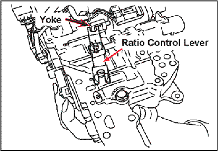 |
- Position the ratio control valve lever so that it is
engaged over the yoke on the stepper motor. Push
the ratio control lever inward toward the valve body.
|
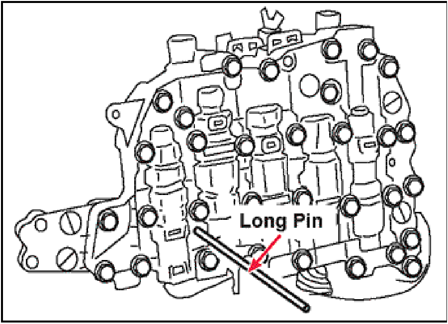 |
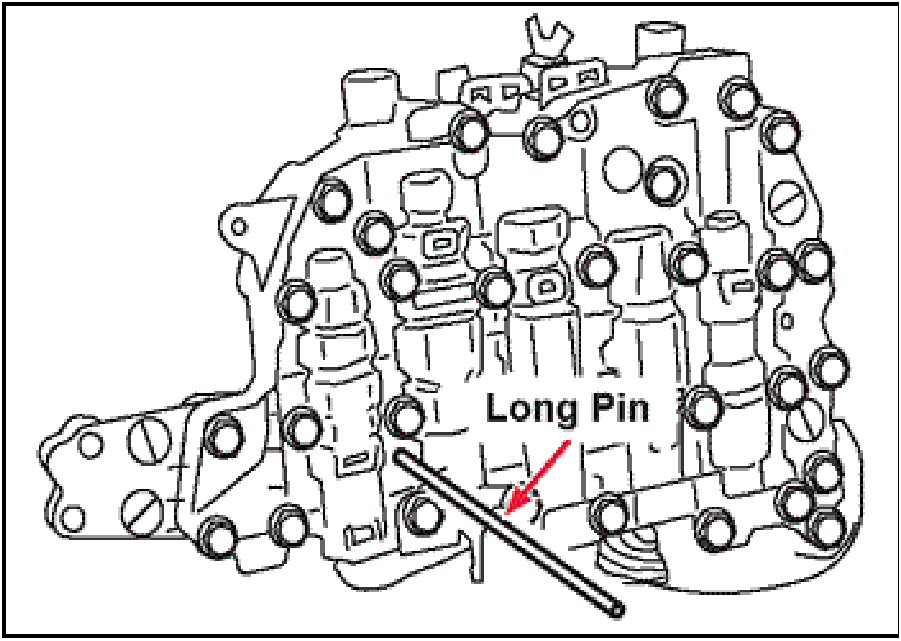
- While holding the ratio control lever in, insert the long
pin used in disassembly into the hole in the valve body.
|
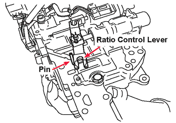 |
- Verify the ratio control valve lever is securely
positioned behind the pin.
|
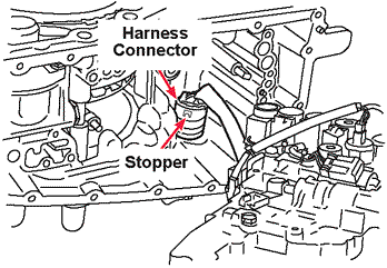 |
- Install the harness connector into the transaxle case.
Push the harness connector toward the outside of the
transaxle case until the stopper is fully seated.
Be careful not to damage the 0-ring.
|
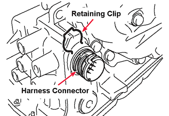 |
- Install the retaining clip into the groove on the harness
connector.
|
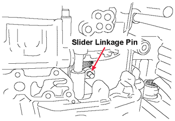 |
- Locate the slider linkage pin. When installing the
valve body, the cutout in the ratio control lever must
engage with the slider linkage pin.
|
 |
- While holding the end of the long pin, install the valve
body into the case making sure the ratio control valve
linkage engages the pin on the slider linkage and that
the valve body seats on to the dowel pins mounted in
the transaxle case.
|
 |
- While holding the valve body against the transaxle
case surface, install the one SHORT valve body
mounting bolt into the location indicated and tighten it
just enough to keep the valve body on the dowel pins
1 — Short Bolt — 44 mm (1.73 in.)
|
 |
- Install the remaining ten LONG valve body mounting
bolts into the locations indicated finger tight only at this
time.
10 — Long Bolts — 54 mm (2.13 in.)
Remove the long pin (installed in step 128) from the
valve body.
Tighten all valve body bolts to 7.9Nm (70 in-lbs.).
|
 |
- Install the oil strainer mounting bracket onto the valve
body with its mounting bolts.
Tighten the two bolts to 7.9Nm (70 in-lbs.).
2 — Long Bolts — 25 mm (.984 in.)
|
 |
- Verify the new o-ring is attached on the new oil
strainer (2824A007). Coat the new o-ring with
petroleum jelly, then install the new oil strainer onto
the valve body.
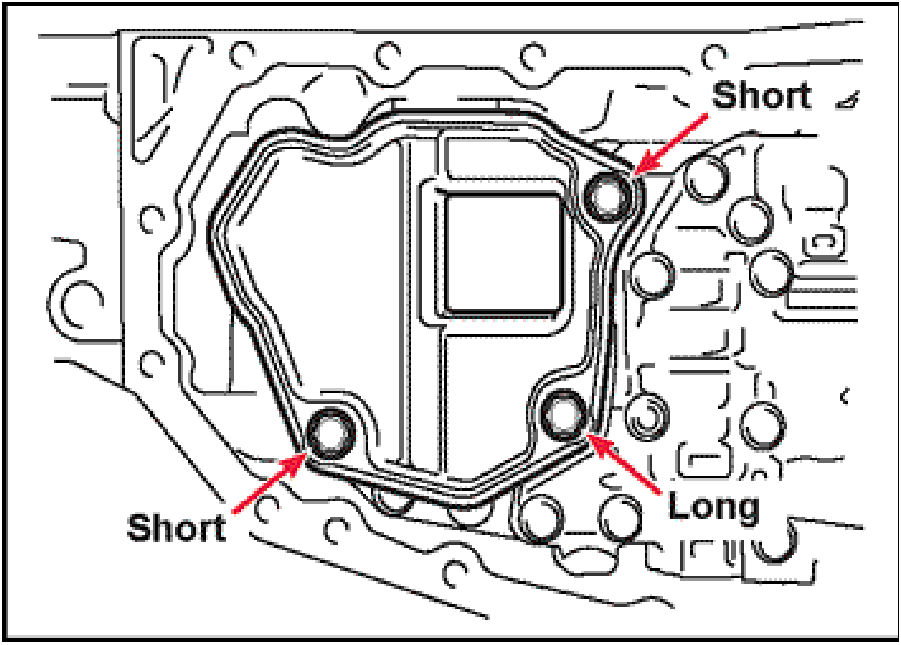
Install the one LONG and two SHORT oil strainer
mounting bolts into the locations indicated. Tighten oil
strainer mounting bolts to 7.9Nm (70 in-lbs.).
1 — Long Bolt — 44 mm (1.73 in.)
2 — Short Bolts — 12 mm (.470 in.)
|
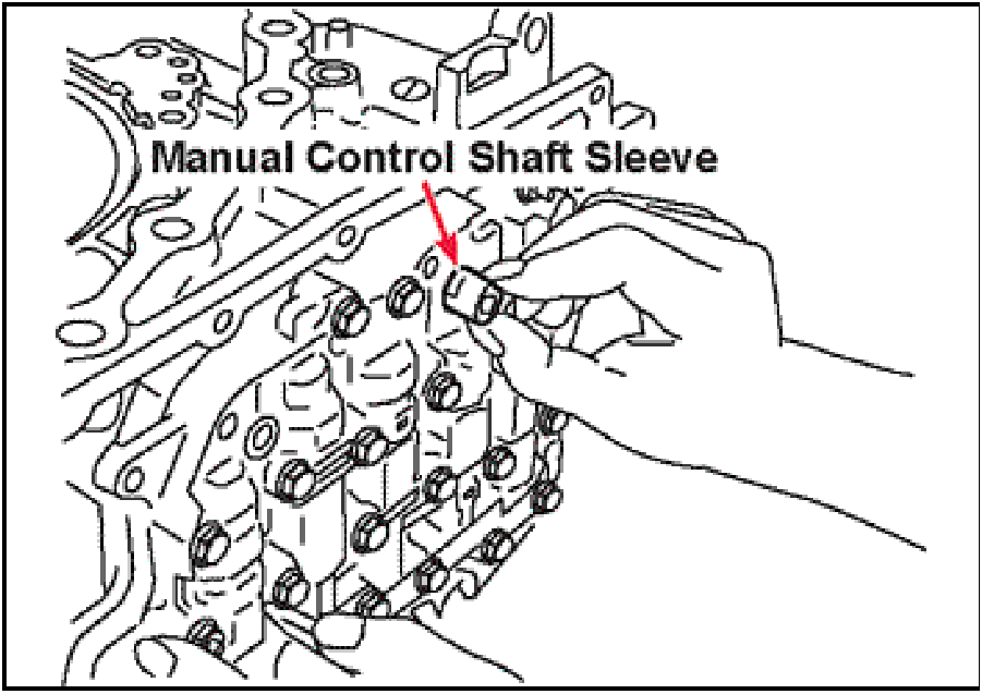 |
- Verify the manual control shaft sleeve is flush with the
valve body surface.
|
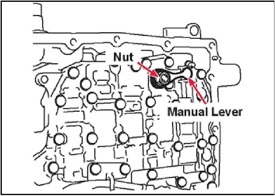 |
- Install the manual control valve lever onto the manual
control shaft, while at the same time, position the
manual control valve to ensure the lever engages the
cutout on the manual control valve.
Install the lock washer and nut.
Tighten the nut to 21 Nm (16 ft-lbs.).
|
 |
- Install the new pan gasket (2705A015) and oil pan
onto the two dowel pins on the transaxle case. Install
the eighteen pan bolts and tighten to 7.9Nm (70
in-lbs.).
18 — Short Bolts — 15 mm (.590 in.)
Install a new drain plug gasket (2705A013). Install the
drain plug into the pan.
|
 |
- Install a new o-ring (8652A017) into the groove on the
secondary pulley speed sensor. Coat the o-ring with
petroleum jelly.
|
 |
- Using a stick magnet, hold the shim into position under
the secondary pulley speed sensor mounting tab
while installing the speed sensor into the transaxle
case.
|
 |
- Install the secondary pulley speed sensor mounting
bolt.
Tighten the bolt to 5.8Nm (52 in-lbs.).
1 — Short Bolt — 17 mm (.669 in.)
|
 |
- Install a new o-ring (8652A017) into the groove on the
primary pulley speed sensor. Coat the o-ring with
petroleum jelly.
|
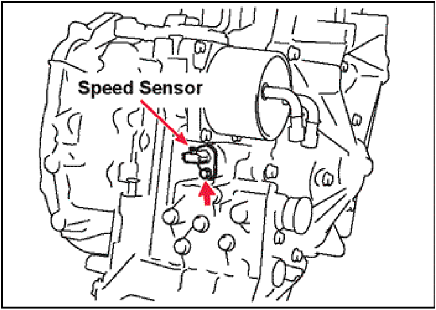 |
- Install the primary pulley speed sensor
Tighten the bolt to 5.8NM (52 in-lbs).
1 — Short Bolt — 17 mm (.669 in.)
|
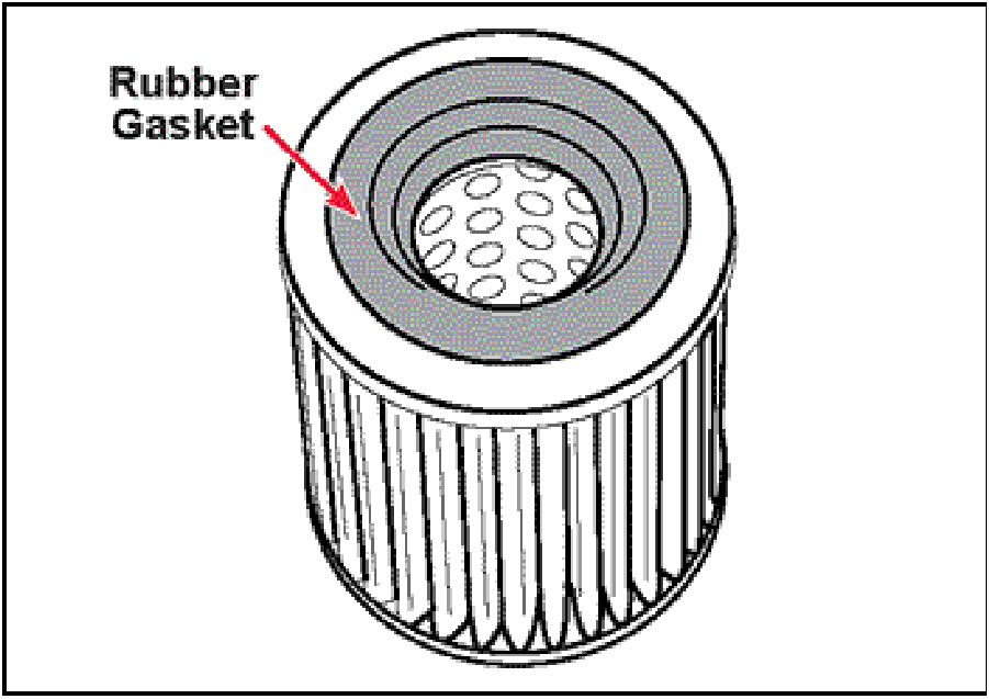 |
- Verify the rubber gasket is installed on the new ATF
warmer / cooler filter (2824A006). Apply a coating of
petroleum jelly to the seal.
|
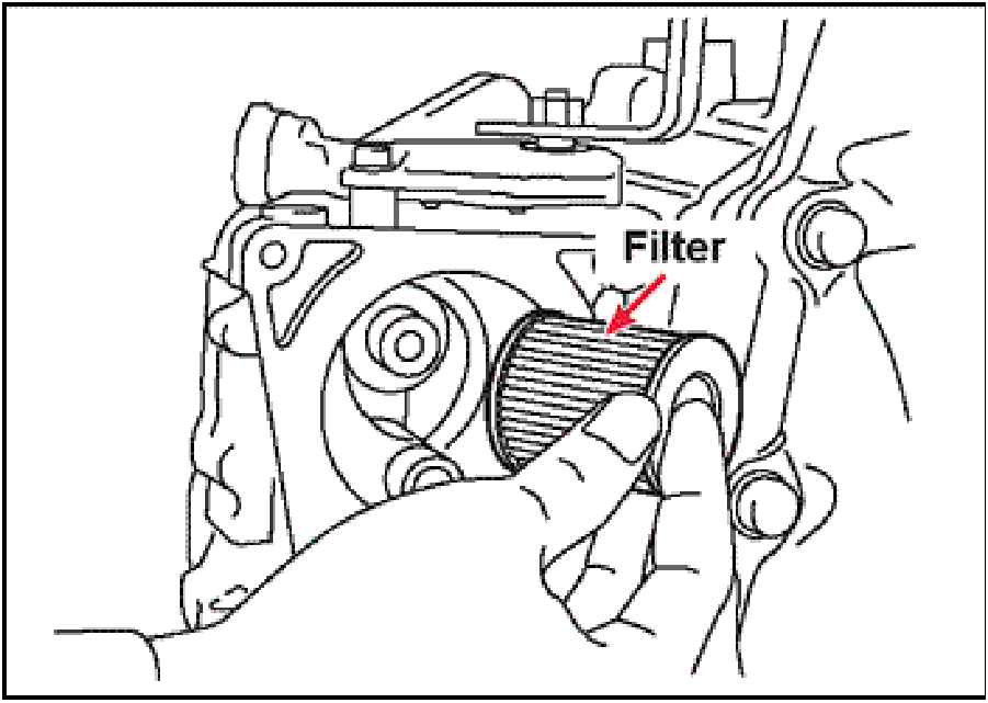 |
- Install the new ATF warmer / cooler filter into the
opening in the transaxle case as shown.
|
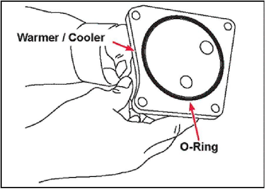 |
- Install a new rubber o-ring (2920A096) in the groove
on the new ATF warmer / cooler. Coat the o-ring with
petroleum jelly.
|
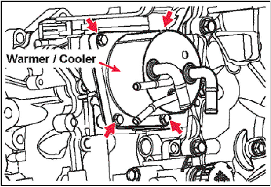 |
- Install the ATF warmer / cooler onto the case with the
four mounting bolts.
Tighten the bolts to 4.1 Nm (37 in-lbs.).
4 — Short Bolts — 24 mm (.944 in.)
|
 |
- Apply a coating of petroleum jelly to the input shaft
o-ring then install the torque converter into the
transaxle case. While lightly pushing inward rotate the
converter back and forth until it is fully seated.
TRANSAXLE FLUSHING
- Once the CVT has been reinstalled in the vehicle,
follow these steps to flush any remaining debris from
transaxle. Do not use an automatic transmission
flushing machine.
|
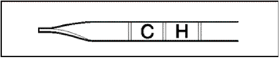 |
- With the engine running, add sufficient
DIA-QUEEN CVTF-J4 transmission fluid to raise
the level above the COLD range on the dipstick.
- Drive the vehicle until the fluid temperature has
reached at least 158°F. (Monitor Data List Item
#5.)
- Drain the fluid from the transaxle.
- Refill the transaxle with CVTF-J4 fluid.
- Drive the vehicle for 5 minutes.
- Drain the fluid from the transaxle.
- Refill the transaxle with CVTF-J4 fluid
|
This bulletin is supplied as technical information only and is not an authorization to repair. If an affected
vehicle is reported with the described condition, diagnose the condition, repair as described in this bulletin
and submit a normal warranty claim using the following information.
