
|
SUBJECT:
F1CJC/W1CJC CVT-ECU CODING PROCEDURE
|
No: TSB-15-23-001
|
|
DATE: February, 2015
|
|
MODEL: 2015 Outlander
Sport/RVR
|
|
CIRCULATE TO:
|
[ ] GENERAL MANAGER
|
[ X ] PARTS MANAGER
|
[ X ] TECHNICIAN
|
|
[ X ] SERVICE ADVISOR
|
[ X ] SERVICE MANAGER
|
[ X ] WARRANTY PROCESSOR
|
[ ] SALES MANAGER
|
PURPOSE
The 2015 Outlander Sport/RVR with 2.0L engine is equipped with a new version of the Continuously
Variable Transaxle (CVT), designated F1CJC (FWD) and W1CJC (AWC). When the valve body, CVT
assembly or CVT-ECU (ECU) is replaced, the ECU must be initialized to the valve body using the
information provided in this TSB.
AFFECTED VEHICLES
2015 Outlander Sport/RVR with 2.0L engine (F1CJC & W1CJC transmissions only)
BACKGROUND
The F1CJC/W1CJC CVT valve body is manufactured with unique coding. In order for the valve body and
ECU to recognize each other, technicians must initialize the ECU with the valve body serial number when
the ECU or valve body (including CVT assembly) is replaced. The information coded into the ECU must
always match the serial number from the valve body.
When replacing the ECU, use the MUT-III to copy the existing valve body information from the ECU being
replaced to the MUT-III, then reverse the process to load the saved information to the new ECU. If
communication with the valve body is not possible, use the steps in the “Learning Procedure (Valve Body
and CVT Replacement)” instructions for downloading the coding file from the MDL, then upload the file
to the ECU.
When replacing a valve body or CVT assembly, you must first download a coding file specific to the valve
body from the MDL to any non-MEDIC PC or laptop, then copy it onto your MEDIC PC and load the
information to the ECU.
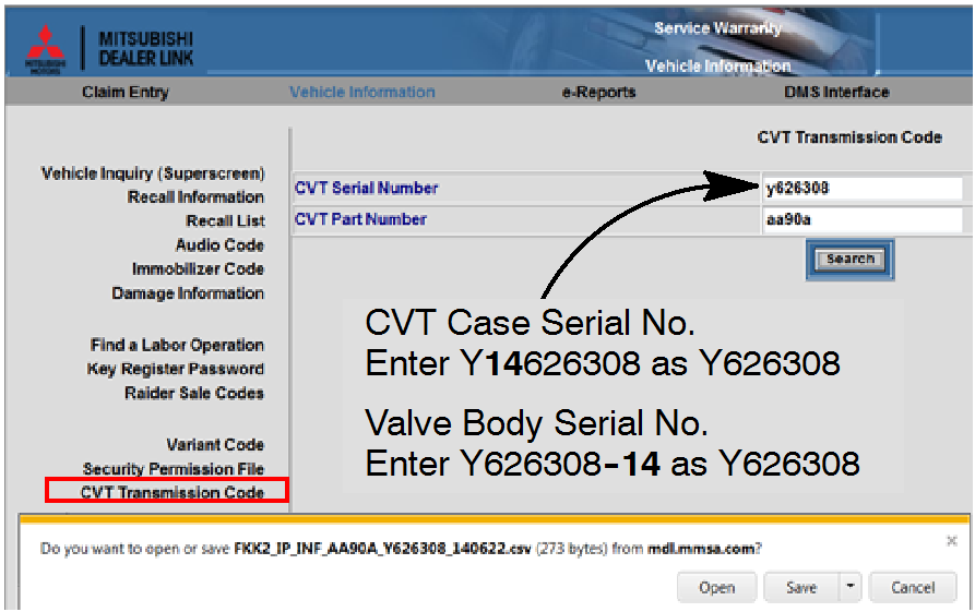
The serial number includes the manufacturer's part number and a manufacturer's serial number along
with other characters. They are located on the valve body and CVT case is shown in the following
illustrations. The serial no. on each part includes a 2 digit year designator (e.g. 14).
!! IMPORTANT !! The year designator is not used when entering the serial number on the MDL. For
example, in this case, the valve body serial number, Y898015-14, is entered as Y898015.
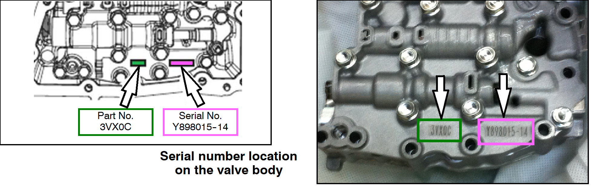
The serial number on the CVT case, Y14898015, is also entered as Y898015.
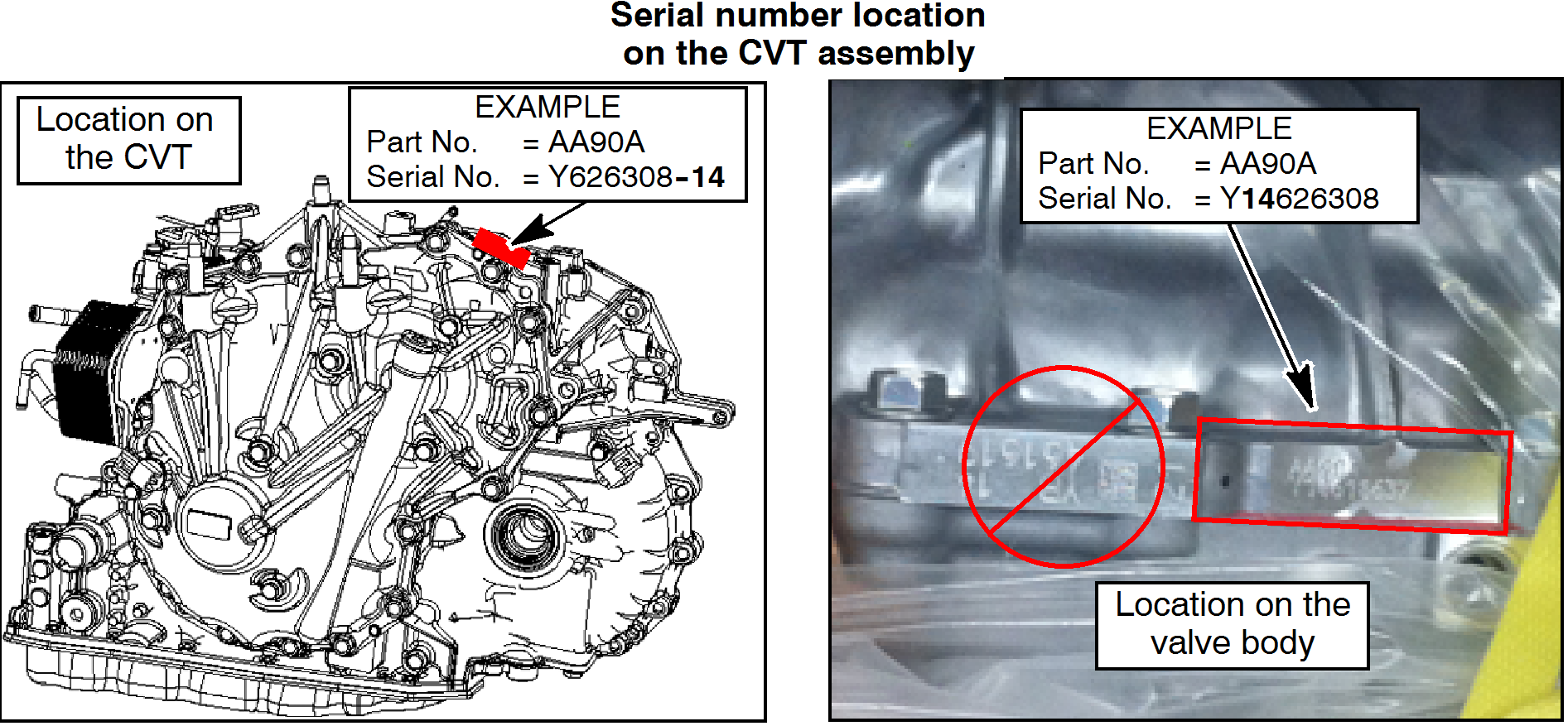
NOTE: The serial number used in the following procedure is as follows:
|
Part No.
AA90A
|
Serial No.
Y626308
|
NOTE: The serial no. format on the valve body is different than the serial
number format on the CVT case. If the valve body serial number reads
Y626308 -14, the CVT case will read Y14626308.
|
PROCEDURE
EQUIPMENT
The following equipment is needed to initialize the CVT-ECU.
- MEDIC Laptop/Tablet computer with A/C power adaptor - 520924, or FZG1MK2.
- VCI (Vehicle Communication Interface) - MB991824 or
VCI LITE - MB992744
- MUT-III main harness 'A' (blue connector at the DLC end) - MB991910.
- USB 2.0 cable - MB991827 OR MB991827.
 |
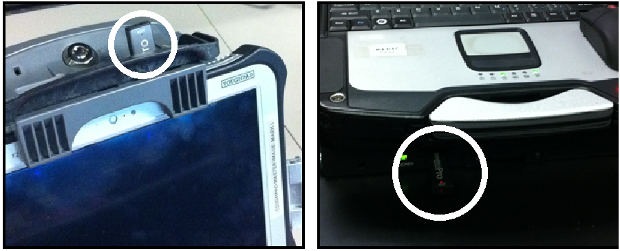
SCAN TOOL PREPARATION
- Connect the MUT-III to the data link connector (DLC).
- Turn the ignition switch to the ON position.
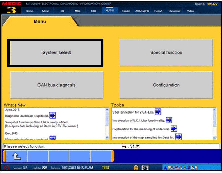
- On the MUT-III main page, choose System Select.
|
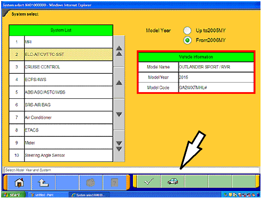 |
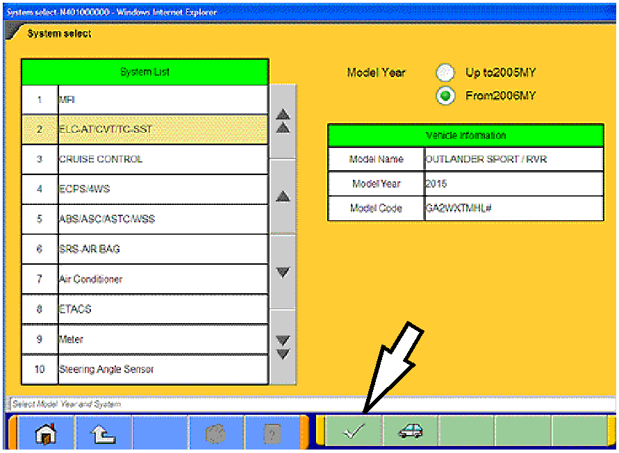
- If the “Vehicle information” does not match the vehicle
being repaired, click on the car icon at the bottom of the
page.
If the “Vehicle information” does match the vehicle
being repaired, continue with the proper initialization
procedure for the repair.
For CVT-ECU Replacement — page 4
For Valve Body or CVT Replacement — page 8
|
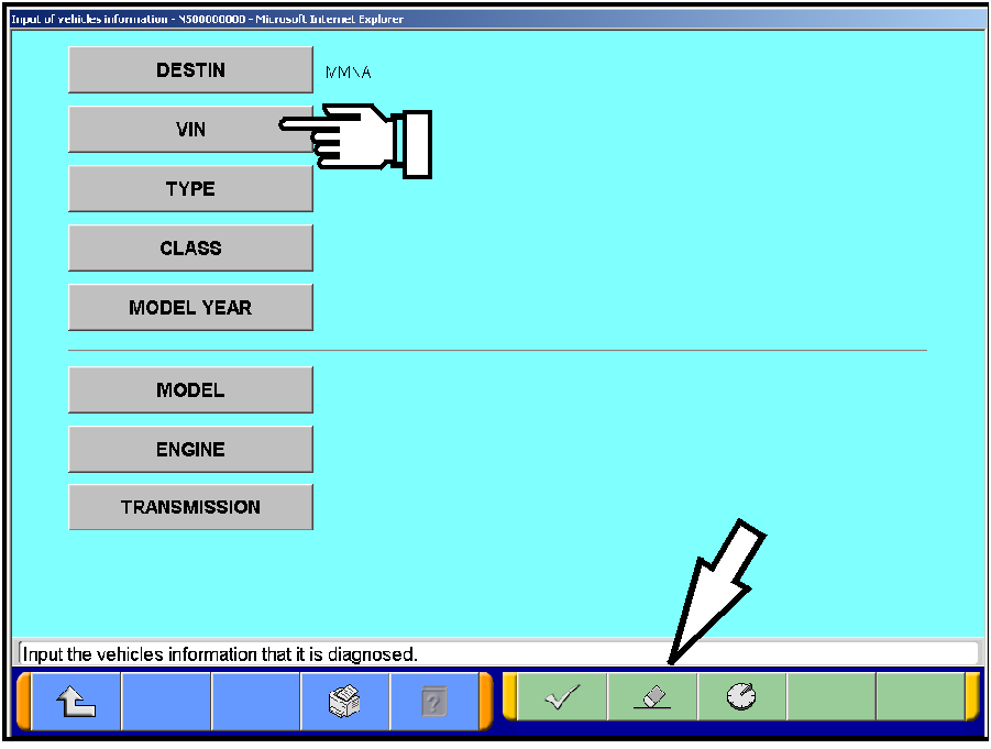 |
- Click the eraser icon at the bottom of the page to
erase vehicle data.
Then click the VIN button.
|
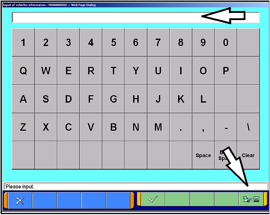 |
- Click the icon in the lower RH corner of the screen
to have MUT-III automatically read the VIN.
If a message appears saying the VIN cannot be
input automatically, manually enter the 17 digit VIN
into the VIN field at the top of the page.
Make sure the VIN is correct and click the check
mark.
|
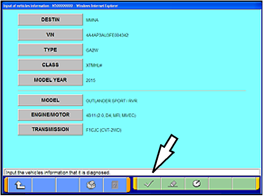 |
- Click on the “TRANSMISSION” button and select
the correct transmission or locate the vehicle class
at the base of the RH “B” pillar by opening the front
passenger's door.
- Confirm all data matches the vehicle and click the
check mark at the bottom of the page to return to
the System Select menu.
|
 |
INITIALIZATION (CVT-ECU REPLACEMENT)
When replacing the CVT-ECU, perform the following
“Learning Procedure” BEFORE installing the new part.
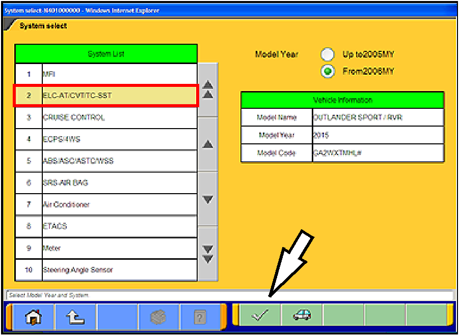
- On the “System List,” highlight ELC-AT/CVT/TC-SST.
Click the check mark at the bottom of the page.
|
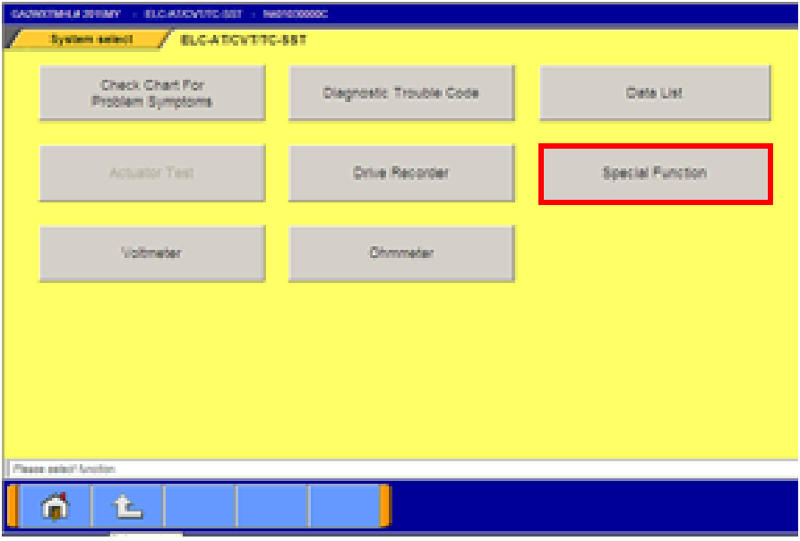 |
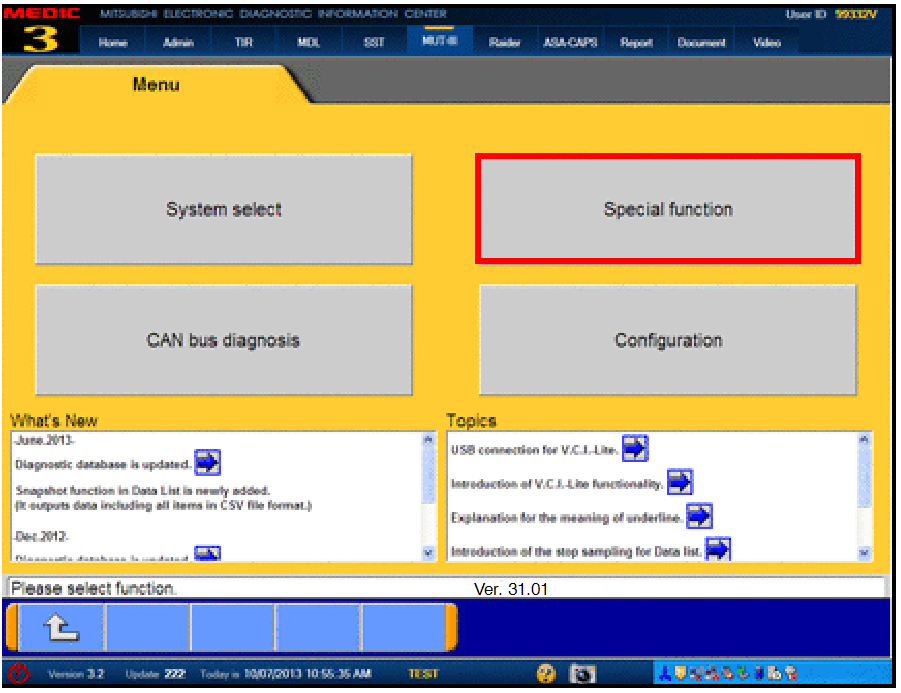
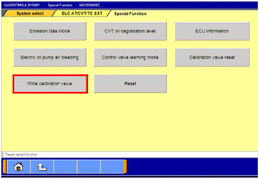
- Select Special Function
|
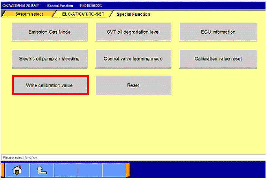 |
- Select “Write calibration value.”
|
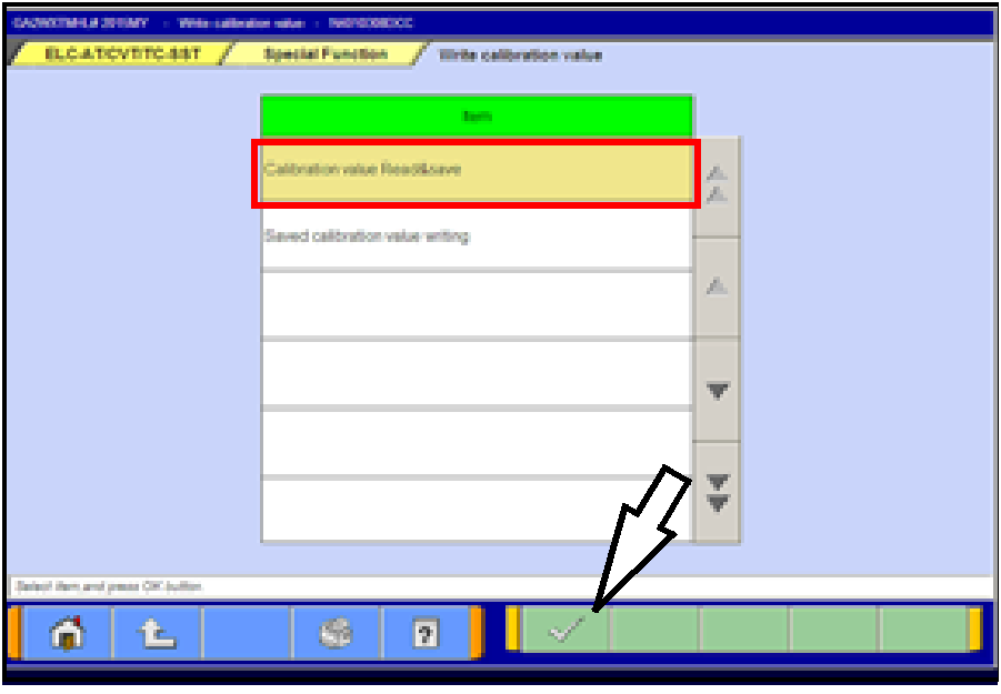 |
- Select “Calibration value Read&Save.”
Click the check mark at the bottom of the page.
|
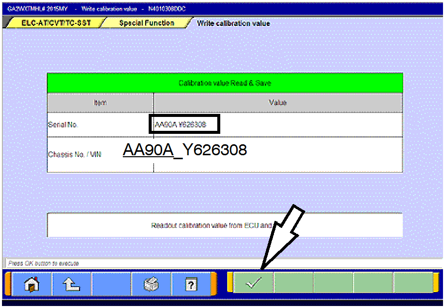 |
- This page will appear and the serial number will display
after a few seconds.
Click the check mark at the bottom of the page.
- Confirm the serial number matches what is printed on
the transaxle case or valve body.
- If it matches, save it to MUT-III by clicking the PC
check mark at the bottom of the page. Go to step
7.
- If it does not match or is not readable, drain the
transaxle oil and remove the oil pan.
- If the serial number stamped on the valve body
does not match, use the instructions to download
the valve body coding from the MDL beginning on
page 8 (Learning Procedure - Valve Body or CVT
Assembly Replacement) and upload to the ECU.
|
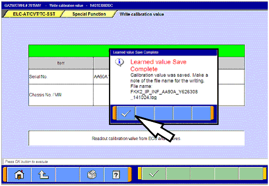 |
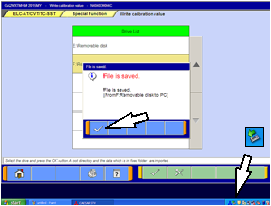
- When successfully saved, the “Learned value Save
Complete” message will appear.
- Confirm the serial number matches what was
displayed during step 5.
- Click the check mark in the message to return to the
“Calibration value Read&Save” page.
- Turn the ignition switch to the LOCK (OFF) position.
|
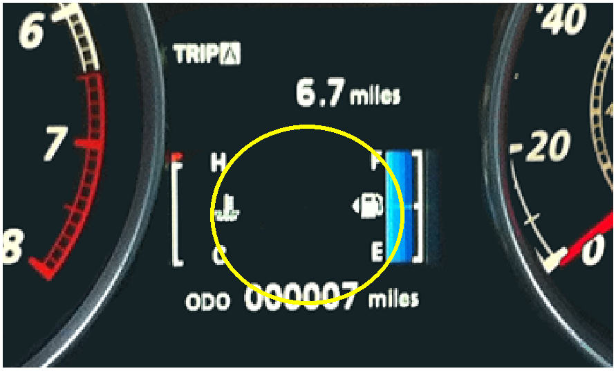 |
- Replace the CVT ECU.
- Confirm the shift selector is in the P or N range and turn
the ignition switch to the ON position.
NOTE: The gear selection SHOULD NOT be
displayed in the MID.
|
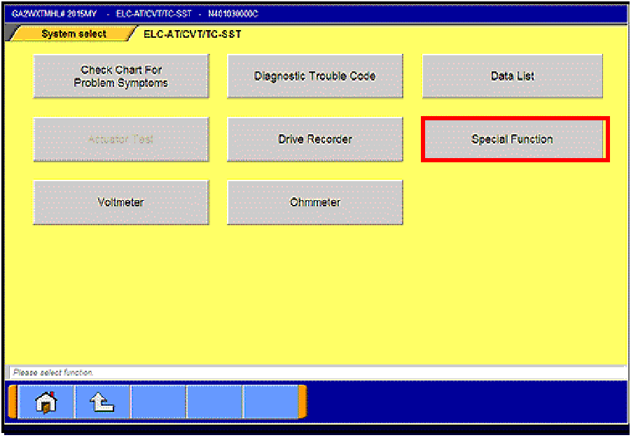 |
- Navigate to the System Select —>
ELC-AT/CVT/TC-SST page. Select Special
Function.
|
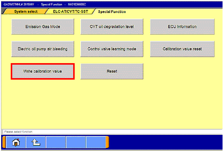 |
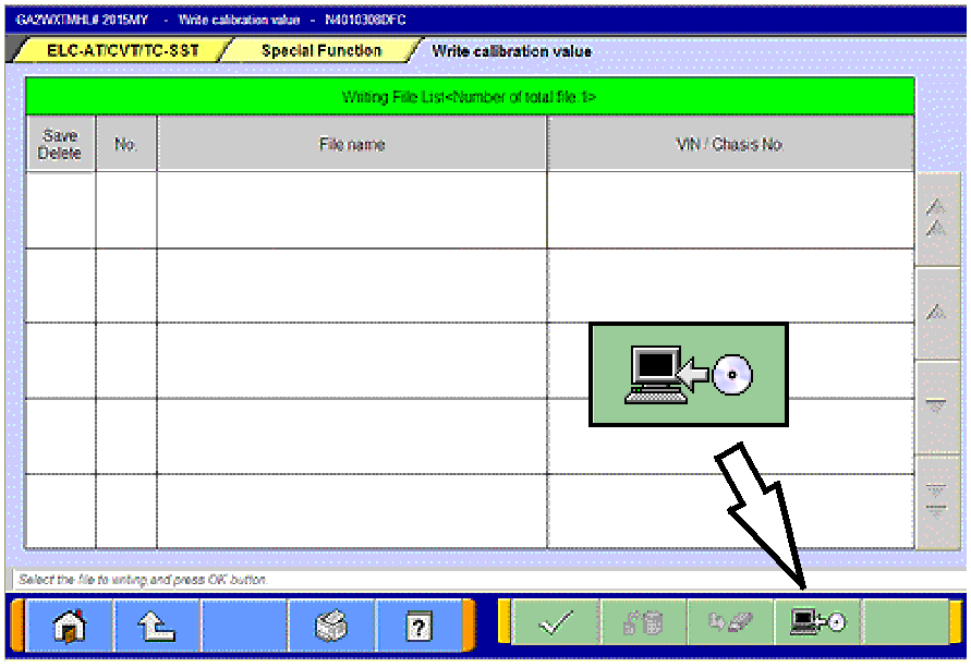
- Select “Write calibration value.”
|
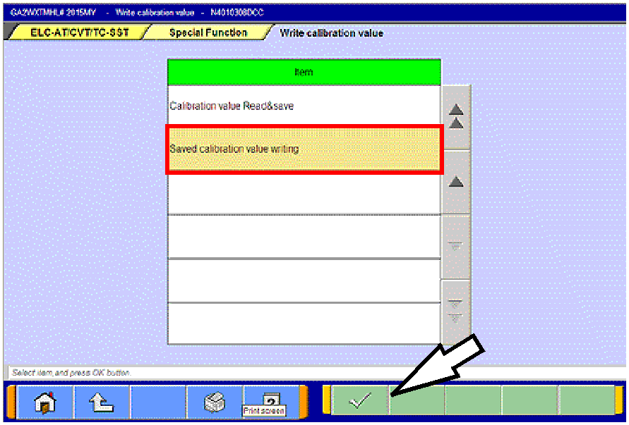 |
- Click on “Saved calibration value writing.”
Click the check mark at the bottom of the page.
|
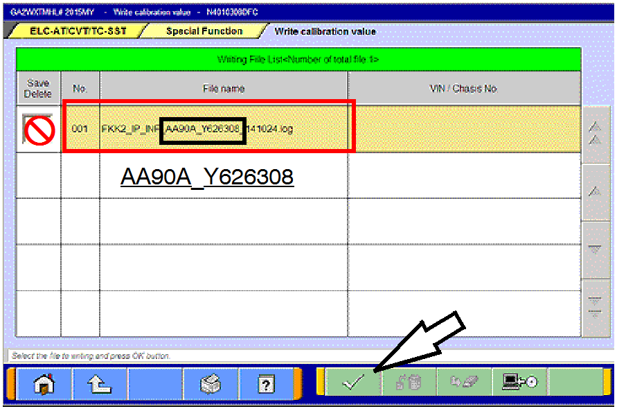 |
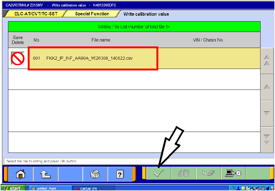
- From the “Writing File List,” click the .log file containing
the serial number that you wrote on the repair order to
highlight it.
Do not check the box in the “Save/Delete” column.
Click the check mark at the bottom of the page.
|
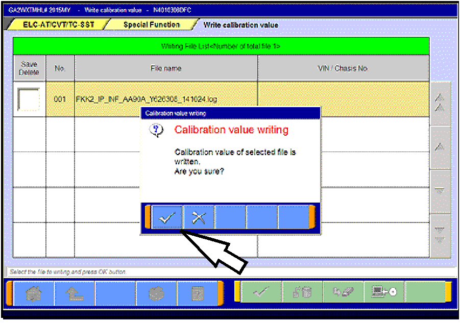 |
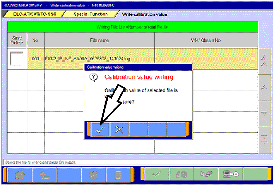
- Click the check mark in the “Calibration Value Writing”
message to begin writing to the ECU.
|
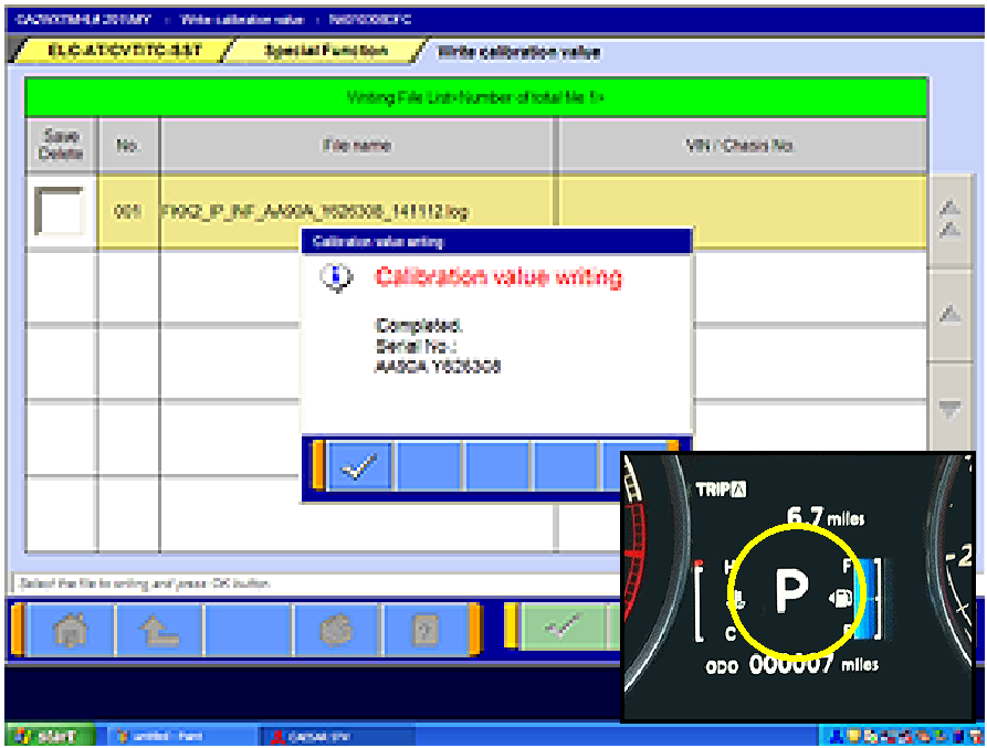 |
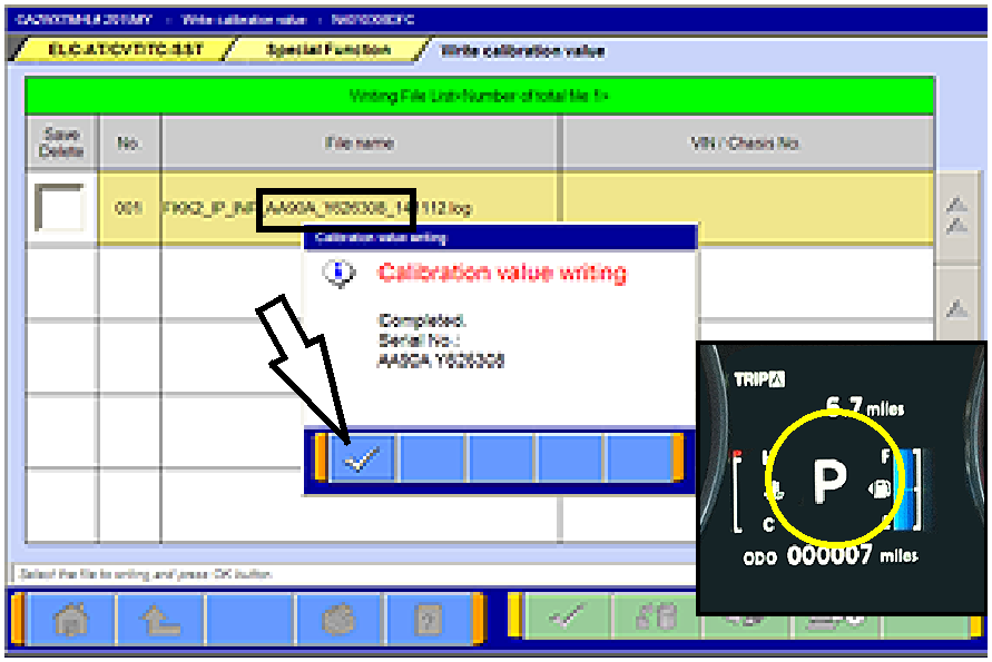
- When writing is successfully completed, the
“Calibration value writing - Complete” message will
display.
NOTE: When successfully completed, the gear
selection SHOULD be displayed in the MID.
Click the check mark to clear the pop-up.
- Turn the ignition switch to the LOCK (OFF) position.
|
- Perform the final learning step. The following conditions must be met for approximately 90 seconds.
You will not be advised when complete.
- To teach the system a meeting point. All of the following conditions must be met for approximately
90 seconds.
- Selector lever position: D
- Engine speed: 500 - 800 rpm (idle)
- The vehicle is stationary.
- There are no abnormalities in the CVT or
related components.
|
- CVT fluid temperature; 40° - 100° C (104° -
212° F)
- The brake pedal is depressed and held for the
entire procedure.
- The accelerator pedal is released for the entire
procedure.
|
- Move the shift selector to P.
- Turn the ignition switch to the LOCK (OFF) position.
When replacing only the TCM, DO NOT complete “Clear CVT Oil Degradation
Level” beginning on page 15. CVT oil degradation should only be cleared if the CVT fluid is
replaced.
LEARNING PROCEDURE (VALVE BODY OR CVT ASSEMBLY REPLACEMENT)
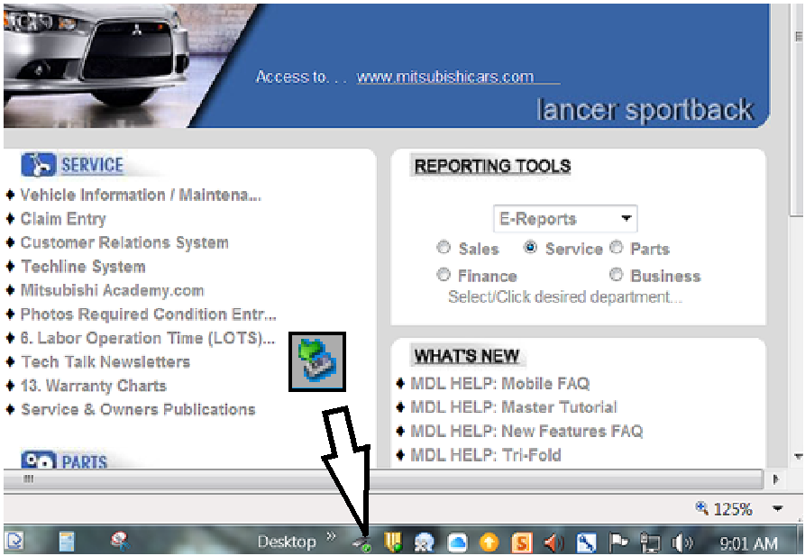
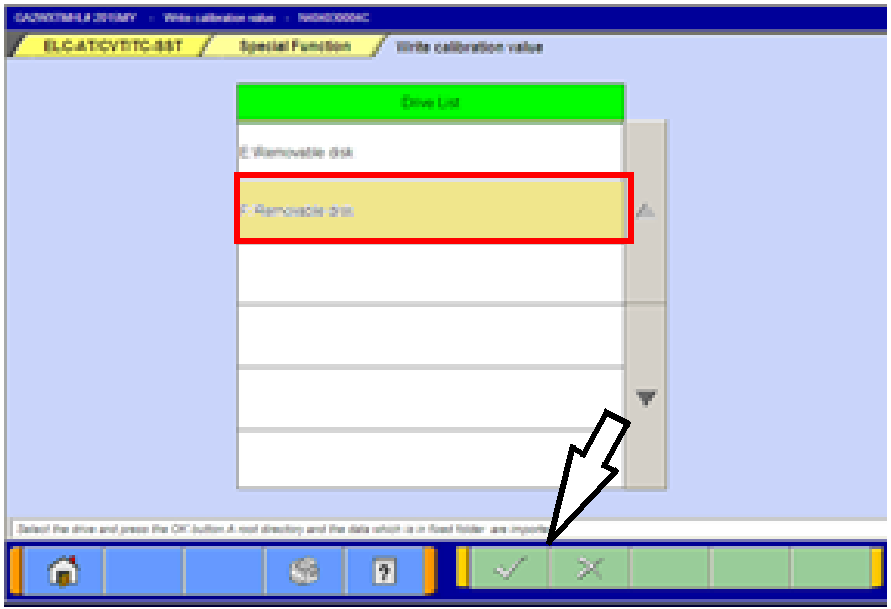
Coding data for the new valve body must be downloaded from the Mitsubishi Dealer Link (MDL) to a PC
and copied to a USB flash drive. The data is then transferred to a MEDIC or MUT-III computer to upload
the coding data for the new valve body to the CVT-ECU.
NOTE: Downloading valve body coding data can be done using any non-MEDIC PC with a USB port .
- If replacing only the valve body, skip the following and continue to the next section.
If replacing the CVT assembly, start the engine and perform the final learning step. The following
conditions must be met for approximately 90 seconds. You will not be advised when complete.
- Selector lever position: D
- Engine speed: 500 - 800 rpm (idle)
- The vehicle is stationary.
- There are no abnormalities in the CVT
or related components.
|
- CVT fluid temperature; 40° - 100° C (104° -
212° F)
- The brake pedal is depressed and held for the
entire procedure.
- The accelerator pedal is released for the entire
procedure.
|
- Shift the selector lever to P.
If replacing the CVT assembly, continue to the procedure “Reset the CVT Oil
Degradation Level“ on page 15.
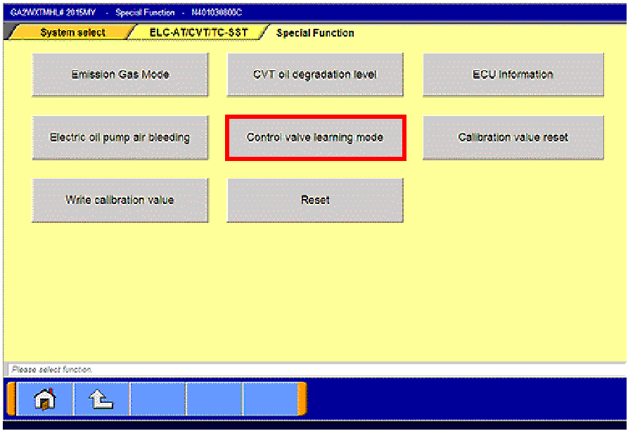
IF REPLACING ONLY THE VALVE BODY, COMPLETE THE FOLLOWING “CONTROL VALVE
LEARNING MODE” PROCEDURE.
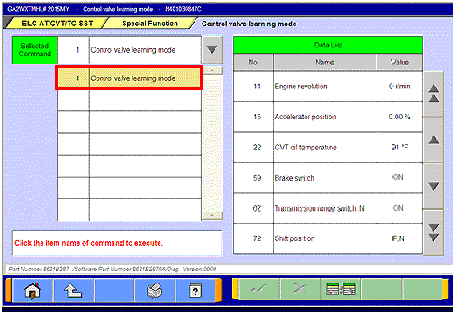
CONTROL VALVE LEARNING MODE
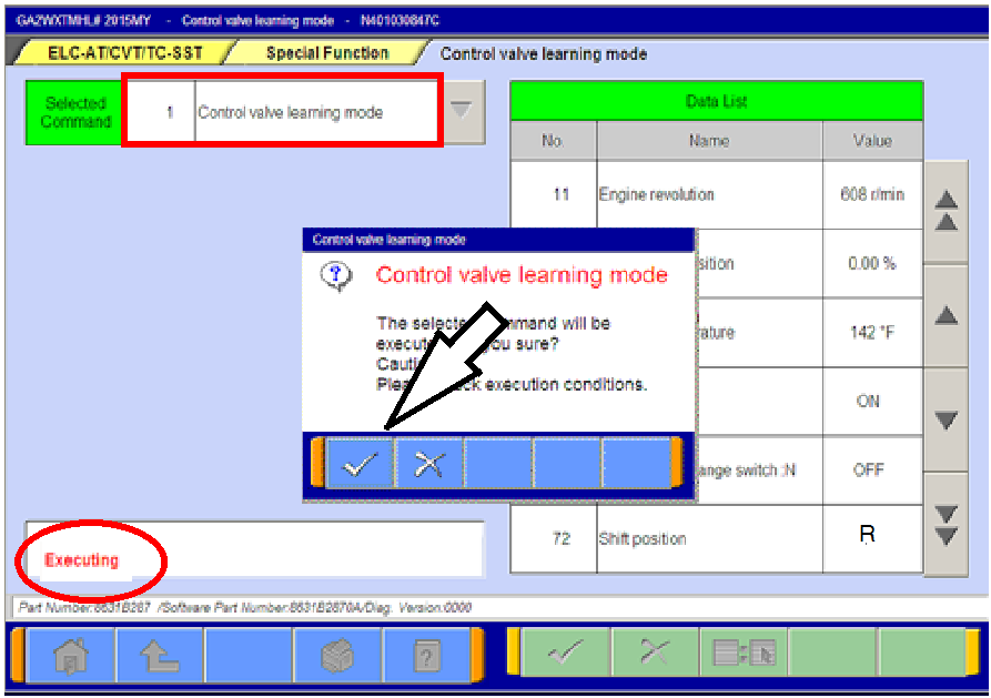
- Start the engine. Set the vehicle to the following conditions:
- Fully depress and hold the brake pedal.
- Selector lever position: N
- Engine speed: 500 - 850 rpm (idle)
- The vehicle is stationary.
- Air conditioning: OFF
|
- CVT fluid temperature; 50° - 100° C (122° -
212° F
- The brake pedal is depressed and held for the
entire procedure.
- The accelerator pedal is released for the entire
procedure.
|
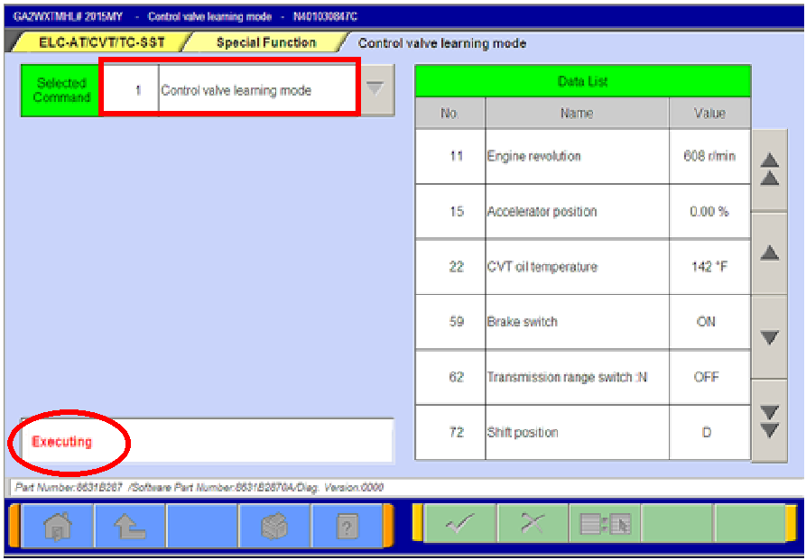
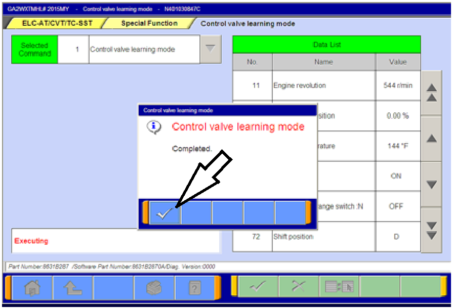
- Start the engine and perform the final learning step. The following conditions must be met for
approximately 90 seconds. You will not be advised when complete.
- CVT fluid temperature; 40° - 100° C (104° -
212° F) must be maintained during this step.
- There are no abnormalities in the CVT
or related components.
- Selector lever position: D
|
- Engine speed: 500 - 800 rpm (idle)
- The vehicle is stationary.
- The brake pedal is depressed and held for the
entire procedure.
- The accelerator pedal is released for the entire
procedure.
|
- Turn the ignition switch to the OFF position.
RESET THE CVT OIL DEGRADATION LEVEL (ONLY IF REPLACING THE CVT ASSEMBLY OR
VALVE BODY)
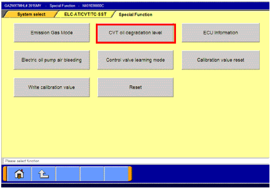 |
- Turn the ignition to the ON position.
- On the MUT-III, navigate to the
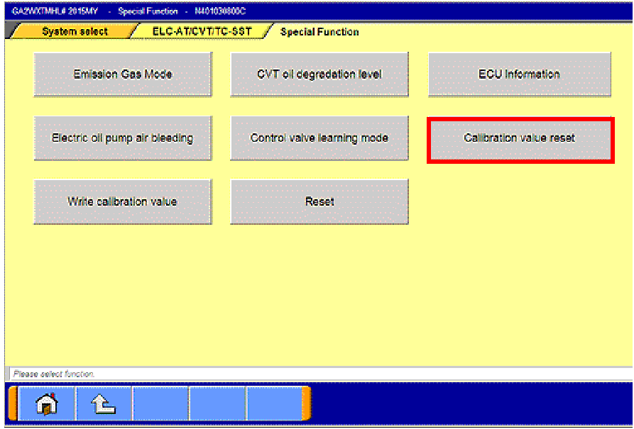
ELC-AT/CVT/TC-SST “Special Function” menu.
- Click the “CVT oil degradation level” button from the
Special Function menu to clear the data from the
CVT-ECU.
|
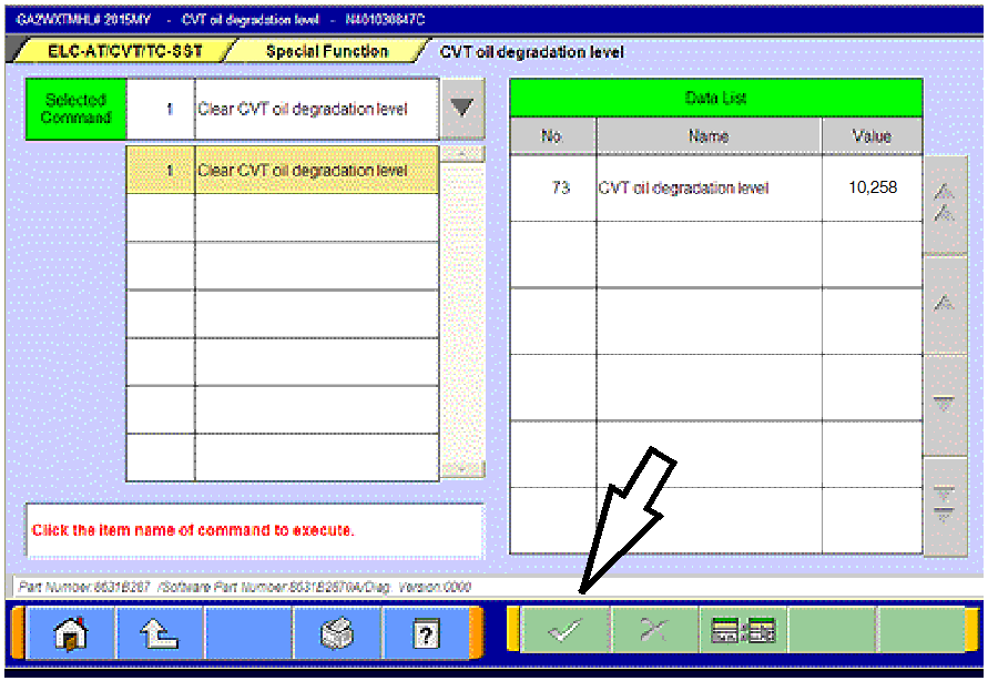 |
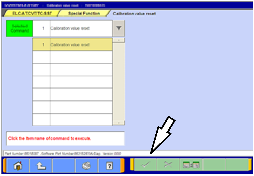
- Select item no. 1, “Clear CVT oil degradation level.”
Click the check mark at the bottom of the page.
|
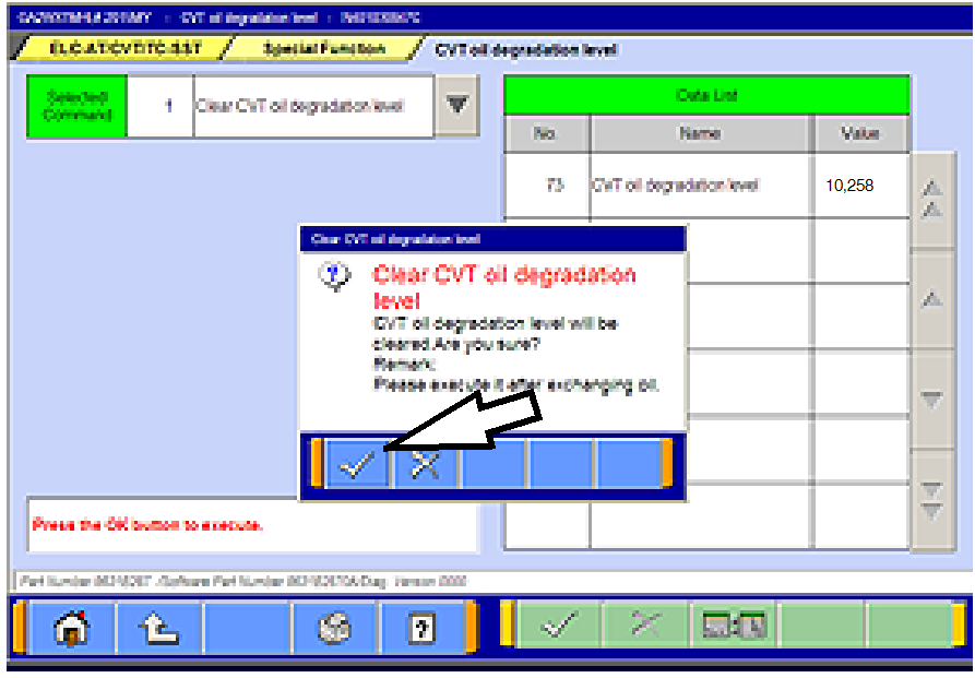 |
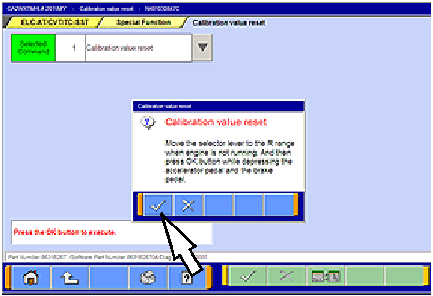
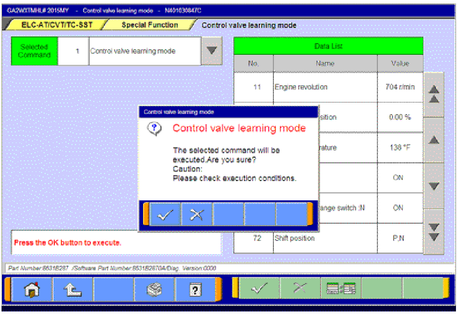
- Click the check mark in the confirmation pop-up to
clear the CVT oil degradation level from the CVT.
|
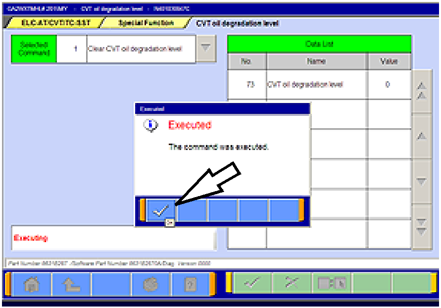 |
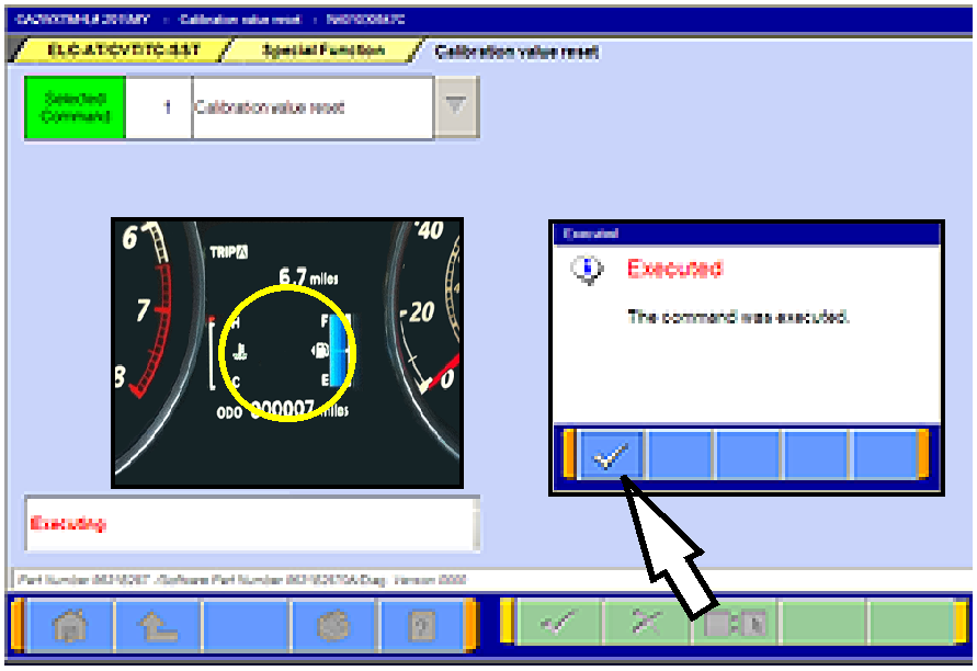
- When successfully executed, this pop-up will display
and the value in the Data List will read 0 (zero).
Click the check mark to clear the window.
- Click the up arrow at the bottom of the page to return
to the Special Functions menu.
|
PARTS INFORMATION
Parts are not required for this procedure.
WARRANTY INFORMATION
This TSB provides technical information only. For warranty claim submission, refer to the Warranty
Labor Operations Time Schedule for labor operation numbers and allowed labor times.
Copyright 2015, Mitsubishi Motors North America, Inc.
| The information contained in this bulletin is subject to change. For the latest version of this document, go to the Mitsubishi Dealer Link, MEDIC, or the Mitsubishi Service Information website (www.mitsubishitechinfo.com).
|

