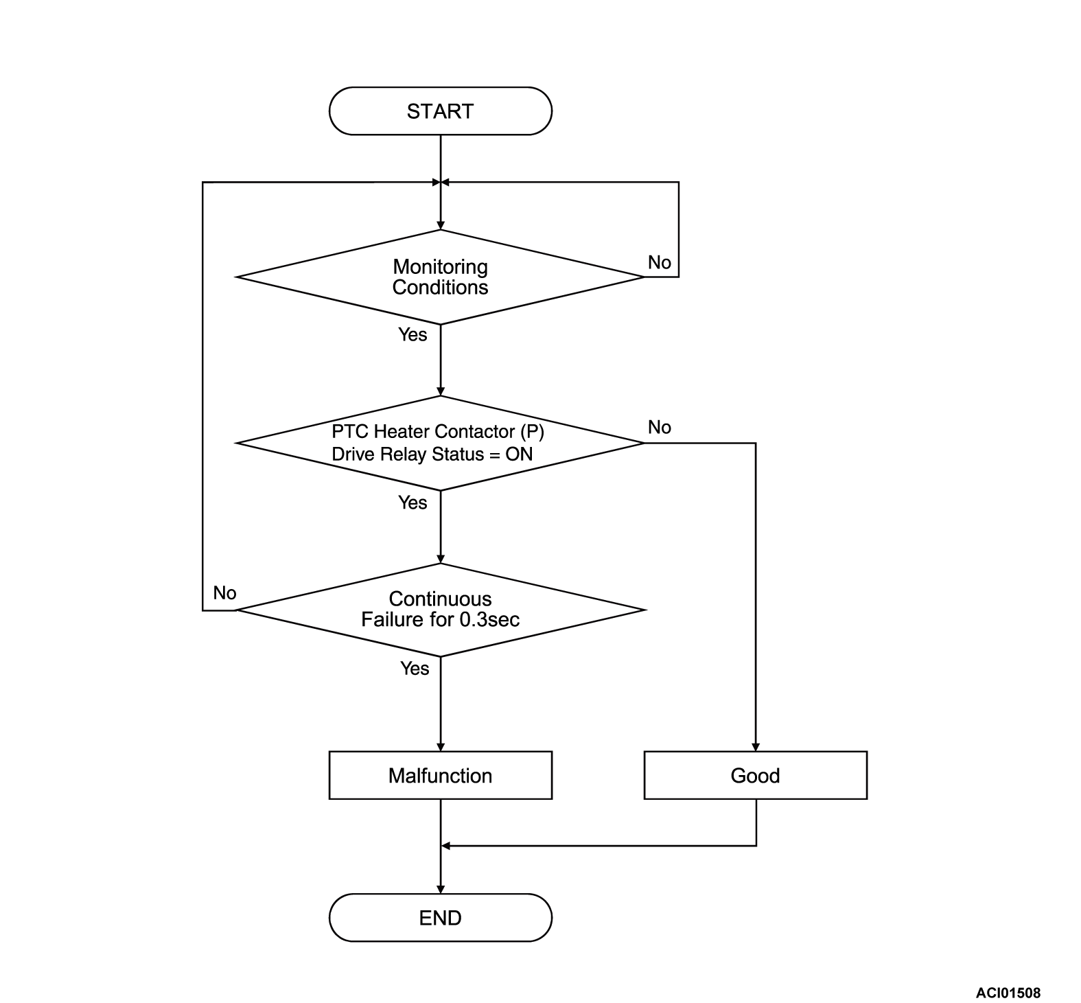
DTC P1EF0: PTC Heater Relay(1) Circuit High
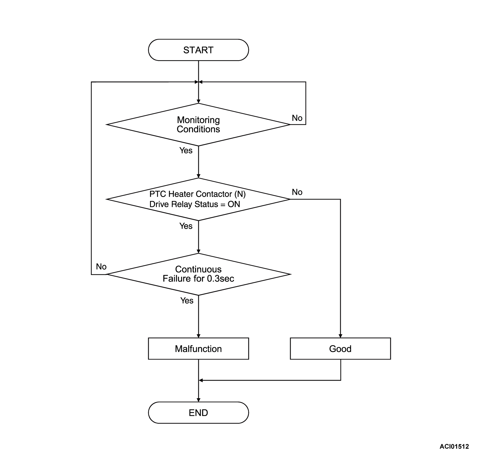
DTC P1EF3: PTC Heater Relay(2) Circuit High
DTC P1EF3: PTC Heater Relay(2) Circuit High
| caution | Before replacing the ECU, ensure that the communication circuit is normal. |
MONITOR EXECUTION
- Continuous
MONITOR EXECUTION CONDITIONS (Other monitor and Sensor)
Other Monitor (There is no DTC set in memory for the item monitored below)
- Not applicable
Sensor (The sensor below is determined to be normal)
- Not applicable
DTC SET CONDITIONS
Check Conditions
- Battery management unit (BMU) power supply voltage is 8 volts to 16 volts.
- Time after above conditions satisfy is more than 1 seconds.
- PTC heater contactor (P) drive relay OFF.
Judgment Criterion
- The state of the PTC heater contactor (P) drive relay ON status continues for 0.3 seconds.
Check Conditions
- Battery management unit (BMU) power supply voltage is 8 volts to 16 volts.
- Time after above conditions satisfy is more than 1 seconds.
- PTC heater contactor (N) drive relay OFF.
Judgment Criterion
- The state of the PTC heater contactor (N) drive relay ON status continues for 0.3 seconds.
FAIL-SAFE AND BACKUP FUNCTION
- Not available
PROBABLE CAUSES
- The PTC heater contactor (P) or (N) drive relay is failed
- Open circuit or short to power supply system of PTC heater contactor drive relay (P) or (N) circuit; poor contact of connector.
- The battery management unit (BMU) is failed.
DIAGNOSIS
Required Special Tools
- MB991658: Test harness
STEP 1. Check the PTC heater contactor (P) or (N) drive relay
STEP 2. Measure the resistance at the BMU connector.
(1) Disconnect the BMU connector, and measure at the wiring harness side.
(2) Check the resistance between BMU connector (PRY1 terminal) and body ground.
OK: Continuity exists
(3) Check the resistance between BMU connector (PRY2 terminal) and body ground.
OK: Continuity exists
Is the check result normal?
 Repair the connector(s) or wiring harness.
STEP 3. Using scan tool (M.U.T.-IIISE), check whether the DTC is set again.
Recheck the DTC.
(1) Erase the DTC.
(2) Turn off the power supply mode of the electric motor switch.
(3) Turn on the power supply mode of the electric motor switch.
(4) Check the DTC.
Is the DTC set?
![[Previous]](../../../buttons/fprev.png)
![[Next]](../../../buttons/fnext.png)


