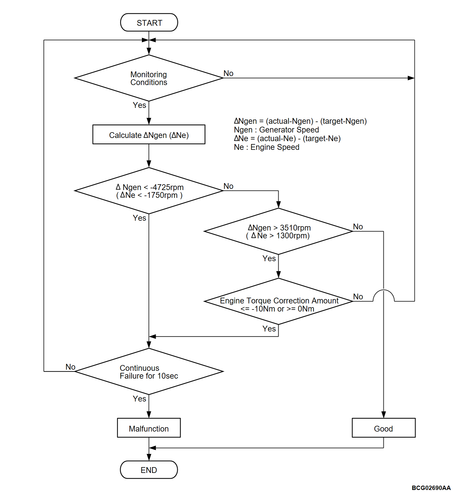
DTC P1508: Generator rotation speed (low)
DTC P1509: Generator rotation speed (high)
DTC P1509: Generator rotation speed (high)
| caution | Whenever ECU is replaced, ensure that the CAN bus lines are normal. |
MONITOR EXECUTION
Continuous
MONITOR EXECUTION CONDITIONS (Other monitor and Sensor)
Other Monitor (There is no temporary DTC stored in memory for the item monitored below)
- Injection valve monitor
- Misfire monitor
- Electronic throttle valve control monitor
- Throttle position sensor (TPS) source monitor
- Electronic throttle valve relay monitor
- Torque monitor
- Electronic throttle valve motor monitor
- Engine control module (ECM) monitor
- CAN-C monitor
Sensor (The sensor below is determined to be normal)
- Mass airflow sensor
- Manifold absolute pressure sensor
- Intake air temperature sensor
- Engine coolant temperature sensor
- Throttle position sensor (TPS)
- Crankshaft position sensor
- Camshaft position sensor
- Barometric pressure sensor
Check Conditions
- When the driving mode is the series driving mode
- When the cold strategy idle control status is OFF
- Engine coolant temperature is 20°C (68°F) or higher
- Generator rotation speed is less than 1350 rpm/sec.
Judgment Criterion <DTC P1508>
- When a state where the target rotation speed of the generator is less than -4725 rpm (the target rotation speed of the engine is less than -1750 rpm) continues for 10 seconds.
Judgment Criterion <DTC P1509>
- When the target rotation speed of the generator is larger than 3510 rpm (the target rotation speed of the engine is larger than 1300 rpm), and when a state where the engine torque correction amount is within the specified range continues for 10 seconds.
PROBABLE CAUSES
- Malfunction of the power drive unit (GCU).
- Malfunction of the PHEV-ECU.
DIAGNOSIS
STEP 1. Using scan tool (M.U.T.-IIISE), check whether the other DTC is set.
Check whether DTC is set in power drive unit (Refer to GROUP 54Db - Troubleshooting, Diagnosis Chart  ).
).
 ).
).Is the DTC set?
STEP 2. Diagnosis of trouble symptom.
Perform the following diagnosis. Correct the defective it.
Is the check result normal?
 Correct the defective it.
![[Previous]](../../../buttons/fprev.png)
![[Next]](../../../buttons/fnext.png)

