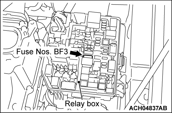
DTC B1762: IOD fuse not seated fully
| caution | Before replacing the ECU, ensure that the power supply circuit, the ground circuit and the communication circuit are normal. |
DTC SET CONDITION
- When voltage at the power supply fuse (fuse No. BF3) drops below 5 V with the electric motor switch ON and then the ACC OFF signal is detected for 5 seconds, the ETACS-ECU will store DTC No. B1762.
TROUBLESHOOTING HINTS
- The fuse No. BF3 may be defective
- The ETACS-ECU may be defective
- The OSS-ECU may be defective
- The wiring harness or connectors may have loose, corroded, or damaged terminals, or terminals pushed back in the connector
DIAGNOSIS
Required Special Tools:
- MB992006: Extra fine probe
- MB991223: Harness set
STEP 1. Check the power supply fuses (fuse No. BF3).
Check the power supply fuses (fuse No. BF3). (Refer to GROUP 00 - How to Use Troubleshooting/Inspection Service Points - Inspection Service Points for a Blown Fuse  .)
.)
 .)
.)Is the fuse in good condition?
STEP 2. Check of short to power supply, short to ground, and open circuit in IODI line between fusible link and ETACS-ECU connector.
STEP 3. Using scan tool (M.U.T.-IIISE), read the OSS DTC.
(1)
| caution | To prevent damage to scan tool (M.U.T.-IIISE), always turn off the power supply mode of the electric motor switch before connecting or disconnecting scan tool (M.U.T.-IIISE). |
(2) Check that the OSS-ECU set a DTC.
Is the DTC set?
STEP 4. Check of short to power supply, short to ground, and open circuit in ACC line between OSS-ECU (ACC) and ETACS-ECU connector.
STEP 5. Recheck for DTC.
Check again if the DTC is set in the ETACS-ECU. Replace the ETACS-ECU.
(1) Erase the DTC.
(2) Press the electric motor switch to turn the power supply mode from "OFF" to "ON."
(3) Check if DTC.
Is the DTC set?
 Replace the ETACS-ECU.
![[Previous]](../../../buttons/fprev.png)
![[Next]](../../../buttons/fnext.png)

