FORCED POWER SUPPLY OUTPUT PROCEDURE
Required Special Tools:
- MB992744: Vehicle communication interface-Lite (V.C.I.-Lite)
- MB992745: V.C.I.-Lite main harness A
- MB992747: V.C.I.-Lite USB cable short
- MB992748: V.C.I.-Lite USB cable long
- MB991958: Scan Tool (M.U.T.-III Sub Assembly)
- MB991824: Vehicles Communication Interface (V.C.I.)
- MB991827: M.U.T.-III USB Cable
- MB991910: M.U.T.-III Main Harness A (Vehicles with CAN communication system)
| caution | To prevent damage to scan tool (M.U.T.-IIISE), always turn the electric motor switch to the OFF before connecting or disconnecting scan tool (M.U.T.-IIISE). |
With OSS, the power supply cannot be turned ON until the certification communication with KOS is complete. However, using the scan tool, the power can be forced ON even when the certification communication with KOS is not completed. Through this process, the error in certification with KOS can be distinguished from the malfunction in power supply. In addition, the process allows the CAN bus diagnosis as well as the reading of diagnostic trouble code, belonging to systems other than OSS, to be performed.
FORCED POWER SUPPLY OUTPUT PROCEDURE
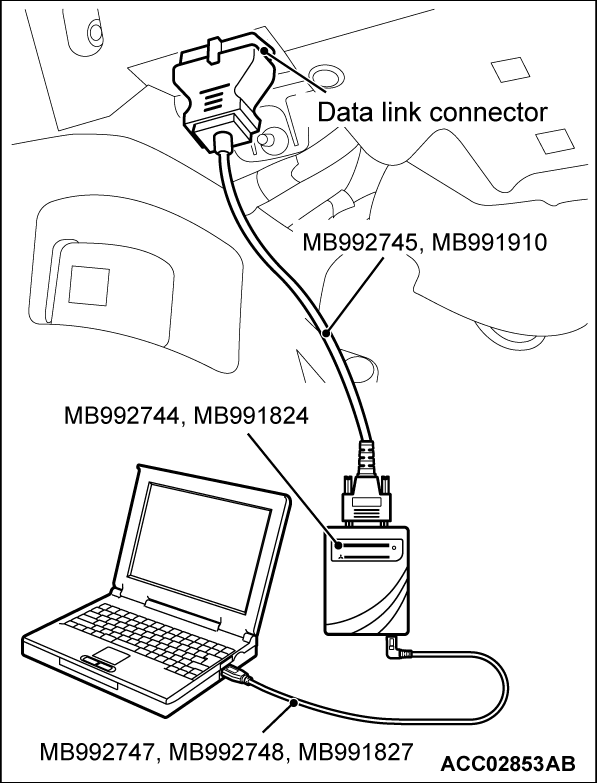
1. Connect special tool MB992747/MB991748 or special tool MB991827 to special tool MB992744 or special tool MB991824 and the personal computer.
2. Connect special tool MB992745 or special tool MB991910 to special tool MB992744 or special tool MB991824.
3. Connect special tool MB992745 or special tool MB991910 to the data link connector.
| note |
|
4. On the "SCAN TOOL (M.U.T.-IIISE) system" selection screen, select "OSS."
5. Select "Special Function" from OSS screen.
6. Select "Forced power supply output" from Special Function screen.
7. From the forced power supply output screen, select the status with which the control is desired. (Selection can be made from IG-ACC, IG-ON, and IG-ST.)
8. On the execution confirmation screen, select OK.
9. While the process is executed, the selected control status is maintained.
| note | During the forced power supply output, the indicator flashes in amber. |
10. To cancel the forced power supply output, select "Forced power supply output (stop)" on the Special Function screen, or operate the electric motor switch.
![[Previous]](../../../buttons/fprev.png)
![[Next]](../../../buttons/fnext.png)
