

DTC U0112: SUB-BMU Signal Timeout
| caution |
- If there is any problem in the CAN bus lines, an incorrect DTC may be set. Prior to this diagnosis, diagnose the CAN bus lines (Refer to GROUP 54C - CAN Bus Diagnostics Table
 ).
- Whenever ECU is replaced, ensure that the CAN bus lines are normal.
|
MONITOR EXECUTION
MONITOR EXECUTION CONDITIONS (Other monitor and Sensor)
Other Monitor (There is no temporary DTC set in memory for the item monitored below)
Sensor (The sensor below is determined to be normal)
DTC SET CONDITIONS
Logic Flow Chart
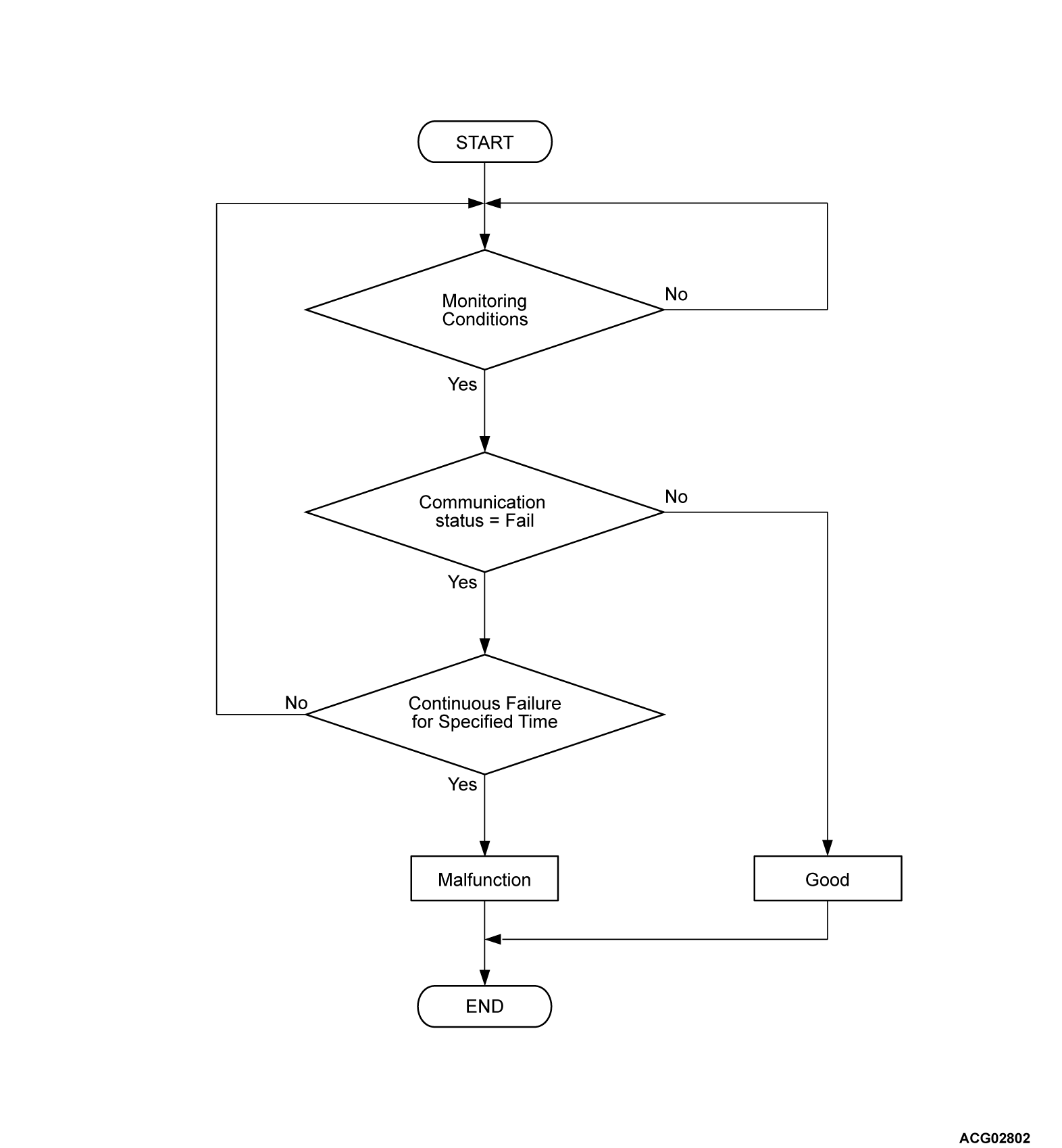
Check Conditions
- battery management unit (BMU) power supply voltage is 8 volts to 16 volts.
- Time after above conditions satisfy is more than 2 seconds.
Judgment Criterion
Unable to receive sub battery management unit (BMU) signals through the CAN bus line for 0.3 second.
OBD-II DRIVE CYCLE PATTERN
Refer to GROUP 54Da - Diagnostic Function - OBD-II Drive Cycle - Pattern 1 .
|
|
FAIL-SAFE AND BACKUP FUNCTION
|
|
|
- The harness and connector is failed.
- CAN line harness damage or connector damage.
- The battery management unit (BMU) is failed.
- The sub-battery management unit [BMU (SUB)] is failed.
|
|
|
STEP 1. Using scan tool (M.U.T.-IIISE), check whether the other DTC is set.
|
|
|
Check whether the DTC P1AD3, P1AD4, P1AD5, P1AD6, P1AD7, P1AD9, P1ADA, P1ADB, P1ADC or P1ADD is set.
|
|
|
 Inspection chart for DTC (Refer to ).
|
|
|
|
|
|
 Go to Step 2.
|
|
|
|
|
|
STEP 2. Check of open circuit, short to ground circuit, short to power supply circuit and damage in CNBL, CNBH line between main drive lithium-ion battery connector and battery management unit (BMU).
|
|
|
Q.
Is the check result normal?
|
|
|
Go to Step 3.
|
|
|
|
|
|
Repair the connector(s) or wiring harness.
|
|
|
|
|
|
STEP 3. Measure the resistance at the D-33 main drive lithium-ion battery connector.
|
|
|
(1)Disconnect the connector, and measure at the wiring harness side.
|
|
|
(2)Check the resistance between the D-33 main drive lithium-ion battery connector terminal No.5 and terminal No.6.
OK: 100 - 140 Ω
|
|
|
Q.
Is the check result normal?
|
|
|
Go to Step 4.
|
|
|
|
|
|
Repair the connector(s) or wiring harness.
|
|
|
|
|
|
STEP 4. Check of open circuit, short to ground circuit, short to power supply circuit and damage in CANL, CANH line between main drive lithium-ion battery connector and sub-battery management unit [BMU (SUB)].
|
|
|
Remove the battery tray cover (Refer to ).
|
|
|
Q.
Is the check result normal?
|
|
|
Go to Step 5.
|
|
|
|
|
|
Repair the connector(s) or wiring harness.
|
|
|
|
|
|
STEP 5. Measure the resistance between the D-33 main drive lithium-ion battery connector and the sub-battery management unit [BMU (SUB)].
|
|
|
(1)Disconnect the connector, and measure at the wiring harness side.
|
|
|
(2)Measure the resistance between the following terminals.
- Between the D-33 main drive lithium-ion battery connector (terminal No.6) and the battery management unit (BMU) connector (terminal CANL).
- Between the D-33 main drive lithium-ion battery connector (terminal No.5) and the battery management unit (BMU) connector (terminal CANH).
OK: Continuity exist (2 Ω or less)
|
|
|
Q.
Is the check result normal?
|
|
|
Go to Step 6.
|
|
|
|
|
|
Repair the connector(s) or wiring harness.
|
|
|
|
|
|
STEP 6. Check of open circuit, short to ground circuit, short to power supply circuit and damage in IGCT line between main drive lithium-ion battery connector and sub-battery management unit [BMU (SUB)].
|
|
|
Q.
Is the check result normal?
|
|
|
Go to Step 7.
|
|
|
|
|
|
Repair the connector(s) or wiring harness.
|
|
|
|
|
|
STEP 7. Check of open circuit, short to power supply circuit and damage in GND line between main drive lithium-ion battery connector and sub-battery management unit [BMU (SUB)].
|
|
|
Q.
Is the check result normal?
|
|
|
Go to Step 8.
|
|
|
|
|
|
Repair the connector(s) or wiring harness.
|
|
|
|
|
|
STEP 8. Using scan tool (M.U.T.-IIISE), check whether the DTC is set again.
|
|
|
(2)Turn off the power supply mode of the electric motor switch.
|
|
|
(3)Turn on the power supply mode of the electric motor switch.
|
|
|
Replace the sub-battery management unit [BMU (SUB)] (Refer to ). Then go to Step 9.
|
|
|
|
|
|
The trouble can be an intermittent malfunction (Refer to GROUP 00, How to Cope with Intermittent Malfunction ).
|
|
|
|
|
|
STEP 9. Test the OBD-II drive cycle.
|
|
|
(1)Carry out a test drive with the drive cycle pattern. Refer to GROUP 54Da - Diagnostic Function - OBD-II Drive Cycle - Pattern 1 .
|
|
|
(2)Check if the DTC is set.
|
|
|
Retry the troubleshooting.
|
|
|
|
|
|
The inspection is complete.
|
|
|
|
