

DTC P0D2F: Front
motor drive voltage sensor fails (short to ground, open circuit)
| danger |
- When servicing the high voltage
system parts, always shut off the high voltage by removing the service plug (Refer to
 ).
- When servicing the high voltage system parts, always wear the protective equipment or
armor to measure the high voltage (Refer to ).
|
MONITOR EXECUTION
MONITOR EXECUTION CONDITIONS (Other monitor and Sensor)
Other Monitor (There is no temporary DTC stored in memory
for the item monitored below)
Sensor (The sensor below is determined to be normal)
DTC SET CONDITIONS
Logic Flow Chart
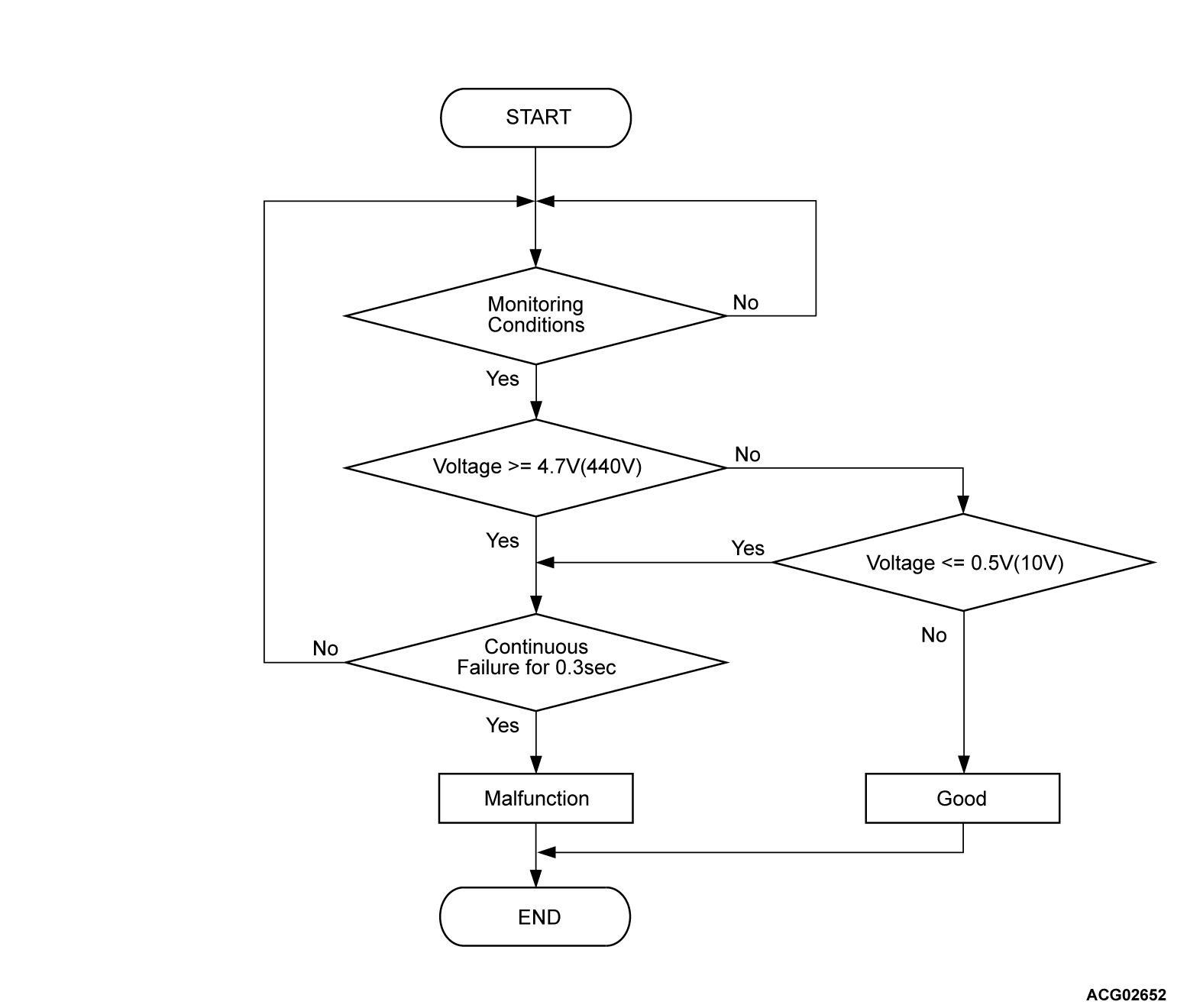
Check Conditions
The vehicle status is propulsion system active.
Judgment Criterion
Change of the power drive unit (FEMCU) inverter voltage sensor voltage is less than
0.5 volt (10 volts) for 0.3 second.
OBD-II DRIVE CYCLE PATTERN
Refer to Diagnostic Function - OBD-II Drive
Cycle - Pattern 1 .
PROBABLE CAUSES
- Malfunction of the power drive unit (FEMCU)
- The battery pack fails
- The high-voltage circuit fails
|
|
Required Special Tools
- MB991223: Wiring harness set
- MB992006: Extra fine probe
|
|
|
STEP 1. Using scan tool (M.U.T.-IIISE), check whether
the other DTC is set.
|
|
|
Check if DTC P1037 is set in the REMCU.
|
|
|
 Go to Step 2.
|
|
|
|
|
|
 Go to Step 6.
|
|
|
|
|
|
STEP 2. Check the high-voltage fuse.
|
|
|
| danger |
- Carry out the check on the high-voltage circuit while
reading carefully the precautions on handling a high-voltage vehicle.
- Wear the specified protection equipment during the check.
|
|
|
|
Check the high-voltage fuse (Refer to GROUP 54Dc - On-vehicle Service ).
|
|
|
Q.
Is the check result normal?
|
|
|
Go to Step 3.
|
|
|
|
|
|
Engage the high-voltage fuse securely, or replace it (Refer to Refer to GROUP
54Dc - On-vehicle service ). Then go to Step 9
.
|
|
|
|
|
|
STEP 3. Check the high-voltage circuit.
|
|
|
| danger |
- Carry out the check on the high-voltage circuit while
reading carefully the precautions on handling a high-voltage vehicle.
- Wear the specified protection equipment during the check.
|
|
|
|
Check whether the high-voltage wiring harness is connect securely or damaged.
|
|
|
Q.
Is the check result normal?
|
|
|
Go to Step 4.
|
|
|
|
|
|
Reconnect the high-voltage wiring harness. Then go to Step 9.
|
|
|
|
|
|
STEP 4. Check the high-voltage circuit.
|
|
|
| danger |
- Carry out the check on the high-voltage circuit while
reading carefully the precautions on handling a high-voltage vehicle.
- Wear the specified protection equipment during the check.
|
|
|
|
(1)Remove the service plug (Refer to ).
|
|
|
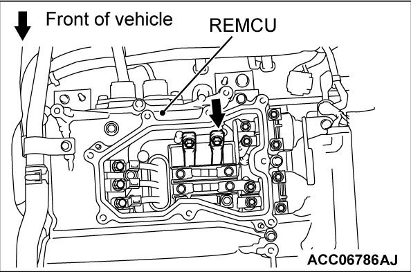
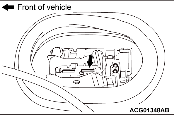
(2)Apply a voltage of 12 V to the CNT- terminal to turn on the charging contactor.
|
|
(3)Connect a high-voltage compatible multimeter between the main drive lithium-ion battery
high-voltage terminal (REMCU) and the main drive lithium-ion battery service plug rear terminal.
OK: Approximately 100 - 164 V
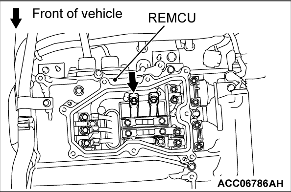
(4)Apply a voltage of 12 V to the CNTP terminal to turn on the charging contactor.
|
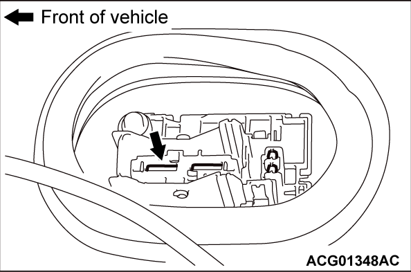
|
(5)Connect a high-voltage compatible multimeter between the main drive lithium-ion battery
high-voltage terminal (REMCU) and the main drive lithium-ion battery service plug front terminal.
OK: Approximately 100 - 164 V
(6)Apply a voltage of 12 V to the CNT+ terminal to turn on the charging contactor.
|
|
(7)Connect a high-voltage compatible multimeter between the main drive lithium-ion battery
high-voltage terminal (REMCU) and the main drive lithium-ion battery service plug front terminal.
OK: Approximately 100 - 164 V
Q.
Is the check result normal?
Go to Step 8.
Go to Step 5.
|
|
|
STEP 5. Check the high-voltage wiring harness and bus bar in the main
drive lithium-ion battery.
|
|
|
(1)Remove the battery tray cover (Refer to GROUP 54Dc - Main Drive Lithium-ion
Battery Disassembly and Assembly ).
|
|
|
(2)Check the high-voltage wiring harness and bus bar in the main drive lithium-ion
battery for looseness or damage.
|
|
|
Q.
Is the check result normal?
|
|
|
Replace the power drive unit (Refer to ). Then assemble
the main drive lithium-ion battery assembly (Refer to GROUP 54Dc - Main Drive Lithium-ion Battery
Disassembly and Assembly ). Then go to Step 9.
|
|
|
|
|
|
Repair the connector(s) or wiring harness. Then go to Step 9.
|
|
|
|
|
|
STEP 6. Check the high-voltage terminal.
|
|
|
| danger |
- Carry out the check on the high-voltage circuit while
reading carefully the precautions on handling a high-voltage vehicle.
- Wear the specified protection equipment during the check.
|
|
|
|
Check that the following cable is tightened to the specified torque.
|
|
|
- Main drive lithium-ion battery front cable (P, N line) connection (power
drive unit side) (Refer to ).
|
|
|
Q.
Is the check result normal?
|
|
|
Go to Step 7.
|
|
|
|
|
|
Tighten the main drive lithium-ion battery front cable (P, N line) to the specified
torque (power drive unit side) (Refer to ). Then go to Step
9.
|
|
|
|
|
|
STEP 7. Check the high-voltage circuit.
|
|
|
| danger |
- Carry out the check on the high-voltage circuit while
reading carefully the precautions on handling a high-voltage vehicle.
- Wear the specified protection equipment during the check.
|
|
|
|
(1)Check that the following cable is tightened to the specified torque.
- Main drive lithium-ion battery front cable (P, N line) connection (main drive
lithium-ion battery assembly side) (Refer to GROUP 54Dc - Main Drive Lithium-ion Battery ).
|
|
|
(2)Check if the main drive lithium-ion battery front cable (P, N line) is damaged.
|
|
|
Q.
Is the check result normal?
|
|
|
Go to Step 8.
|
|
|
|
|
|
NO <Connection failure> : Tighten the main drive lithium-ion battery front cable (P, N line) to the specified torque
(main drive lithium-ion battery assembly side) (Refer to GROUP 54Dc - Main Drive Lithium-ion Battery ).
Then go to Step 9.
|
|
|
|
|
|
NO <Damaged> : Replace the main drive lithium-ion battery front cable (P, N line) (Refer to <Power drive
unit side> and GROUP 54Dc - Main Drive Lithium-ion Battery <Main
drive lithium-ion battery assembly side>). Then go to Step 9.
|
|
|
|
|
|
STEP 8. Test the OBD-II drive cycle.
|
|
|
(1)Carry out a test drive with the drive cycle pattern. Refer to OBD-II Drive Cycle - Pattern
1 .
|
|
|
Replace the power drive unit (Refer to ). Then go
to Step 9.
|
|
|
|
|
|
Intermittent malfunction (Refer to GROUP 00 - How to Use Troubleshooting/Inspection
Service Points - How to Cope with Intermittent Malfunctions ).
|
|
|
|
|
|
STEP 9. Test the OBD-II drive cycle.
|
|
|
(1)Carry out a test drive with the drive cycle pattern. Refer to Diagnostic Function - OBD-II
Drive Cycle - Pattern 1 .
|
|
|
Retry the troubleshooting.
|
|
|
|
|
|
The inspection is complete.
|
|
|
|


