

DTC P0C73: Cooling system fail(1)
| caution |
Whenever ECU is replaced, ensure that the CAN bus lines are normal.
|
MONITOR EXECUTION
Continuous
MONITOR EXECUTION CONDITIONS (Other monitor and Sensor)
Other Monitor (There is no temporary DTC stored in memory for the item monitored below)
Sensor (The sensor below is determined to be normal)
DTC SET CONDITIONS
Logic Flow Chart
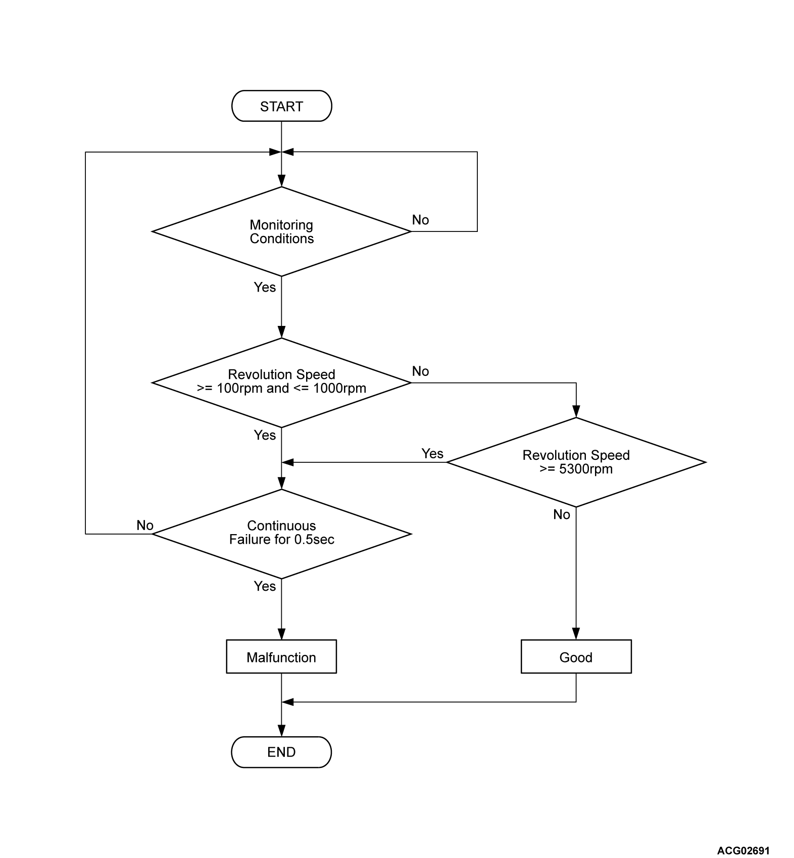
Check Conditions
- The PHEV-ECU power supply voltage is more than 9.0 volts.
- Driving instructions of 30% or more are issued to the electric water pump.
- Time after above conditions satisfy is more than 2 seconds.
Judgment Criterion
- When the rotation speed of 100 rpm or more and 1,000 rpm or less continues for 0.5 seconds
- When the rotation speed of 5,300 rpm or more continues for 0.5 seconds
OBD-II DRIVE CYCLE PATTERN
Refer to Diagnostic Function - OBD-II Drive Cycle - Pattern 3  .
PROBABLE CAUSES
| caution |
This DTC may be settled by temporary air bite into the cooling system.
|
- The motor coolant level is incorrect.
- The motor coolant concentration is incorrect.
- Noise was mixed in the electric water pump rotation signal circuit.
- Frozen coolant.
- Damaged harness or connector.
- Malfunction of the electric water/oil pump relay.
- Malfunction of the electric water pump.
- Malfunction of the PHEV-ECU.
|
|
Required Special Tools
- MB991223: Wiring harness set
- MB992006: Extra fine probe
|
|
|
STEP 1. Coolant level check <Motor coolant>.
|
|
|
Check the amount of motor coolant (Refer to GROUP 14B - On-vehicle Service, Motor Coolant Level Check ).
|
|
|
Q.
Is the check result normal?
|
|
|
 Go to Step 2.
|
|
|
|
|
|
 Inject the motor coolant (Refer to GROUP 14B - On-vehicle Service, Motor Coolant Change ). Then go to Step 7.
|
|
|
|
|
|
STEP 2. Coolant concentration check <Motor coolant>.
|
|
|
Check the coolant concentration (Refer to GROUP 14B - On-vehicle Service, Motor Concentration Check ).
|
|
|
Q.
Is the check result normal?
|
|
|
Go to Step 3.
|
|
|
|
|
|
Adjust the motor coolant concentration between 30 and 60% (service concentration range). Then go to Step 7.
|
|
|
|
|
|
STEP 3. Using scan tool (M.U.T.-IIISE), check the data list.
|
|
|
(1)Turn off the power supply mode of the electric motor switch.
|
|
|
(2)Operate the electric motor switch twice without depressing on the brake pedal and turn on the power supply mode.
|
|
|
(3)Wait at least 5 seconds.
|
|
|
(4)Check that the following data list display contents are normal (Refer to ).
Data list
OK: 500 r/min
|
|
|
Q.
Is the check result normal?
|
|
|
Go to Step 5.
|
|
|
|
|
|
Go to Step 4.
|
|
|
|
|
|
STEP 4. Check the signal line for open or short to ground circuit (electric water pump connector and the PHEV-ECU).
|
|
|
Check the wiring harness between electric water pump connector and the PHEV-ECU connector (terminal WPN).
|
|
|
Q.
Is the check result normal?
|
|
|
Go to Step 5.
|
|
|
|
|
|
Repair the wiring harness or connector. Then go to Step 7.
|
|
|
|
|
|
STEP 5. Check the signal line for open circuit and short to ground circuit (PHEV-ECU connector and electric water pump connector).
|
|
|
Check the wiring harness between PHEV-ECU connector (terminal WP) and electric water pump connector.
|
|
|
Q.
Is the check result normal?
|
|
|
Replace the electric water pump (Refer to GROUP 14B - Water Pump Removal and Installation ). Then go to Step 6.
|
|
|
|
|
|
Repair the wiring harness or connector. Then go to Step 7.
|
|
|
|
|
|
STEP 6. Test the OBD-II drive cycle.
|
|
|
(1)Carry out a test drive with the drive cycle pattern. Refer to Diagnostic Function - OBD-II Drive Cycle - Pattern 3 .
|
|
|
Replace the PHEV-ECU (Refer to ). Then go to Step 7.
|
|
|
|
|
|
The procedure is complete.
|
|
|
|
|
|
STEP 7. Test the OBD-II drive cycle.
|
|
|
(1)Carry out a test drive with the drive cycle pattern. Refer to Diagnostic Function - OBD-II Drive Cycle - Pattern 3 .
|
|
|
Retry the troubleshooting.
|
|
|
|
|
|
The procedure is complete.
|
|
|
|
