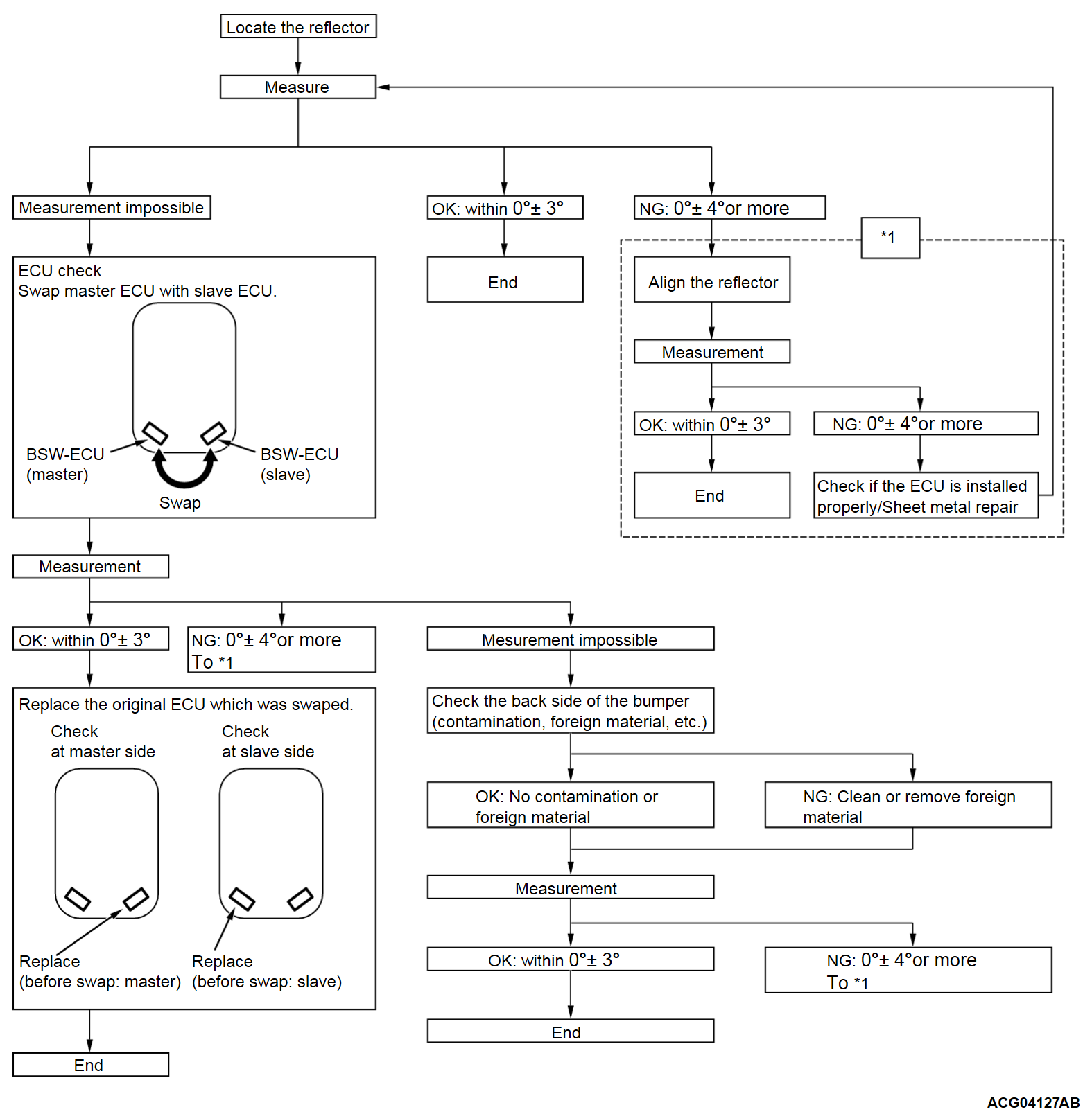
BSW-ECU INSPECTION
| caution | Do not modify or repair the area of the rear bumper surrounding the BSW-ECU. The radar may irradiate incorrectly. |
When any of the followings is carried out, observe the procedure below to check the BSW-ECU.
- BSW-ECU removal and installation
- Modifying the rear bumper assembly
Fabricating a reflector for inspection of the BSW
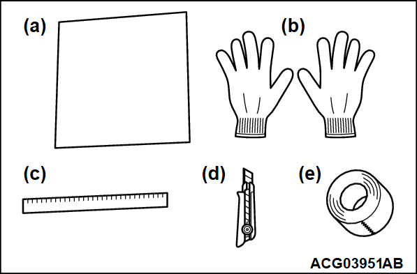
1. Obtain an aluminum plate and the tools below:
What to obtain
- Aluminum plate: 300 mm (11.8 inches) (W), 150 mm (5.9 inches) (H) and 0.5 mm (0.02 inch) (D) or more
note To fabricate the plate easily, we recommend that the plate should be 0.5 mm (0.02 inch) thick. If thinner, the plate may be curved easily. If thicker, it will take longer to fabricate the plate. - Protective gloves
- 300-mm (11.8 inches) long scale
- Knife
- Adhesive tape
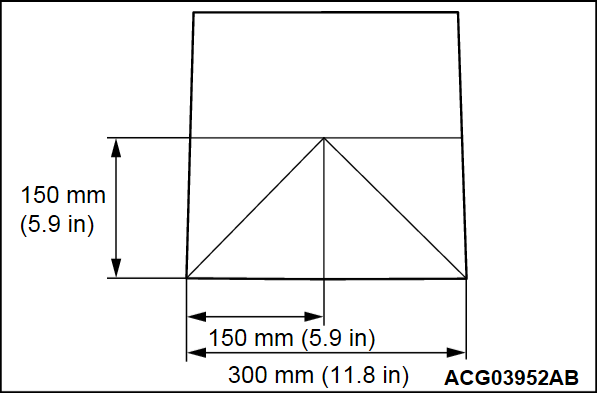
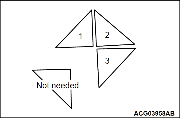
2. Wear protective gloves and scribe the lines on the aluminum plate as shown.
| note |
|
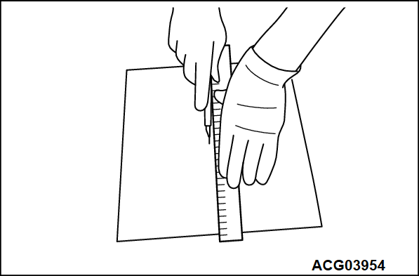
3. Cut the plate according to the steps below:
(1) Align a scale along the scribed line.
(2) Hold the scale securely. Use it as a guide to make a V-groove on the plate with a knife.
(3) Repeat the process above approximately 20 times to deepen the V-groove.
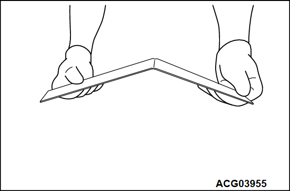
(4) Bend the plate slightly to check that the plate can be bent sharply along the V-groove as shown. If no, the V-groove is too shallow. Repeat step (3).
(5) Bend the plate several times to cut it.
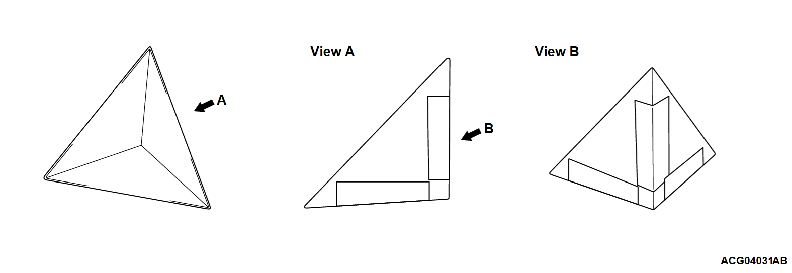
4. Assemble the plate pieces according to the steps below to make a triangular pyramid.
(1) Use three of four plate pieces. If the piece is covered with a protective film, do not peel off it yet.
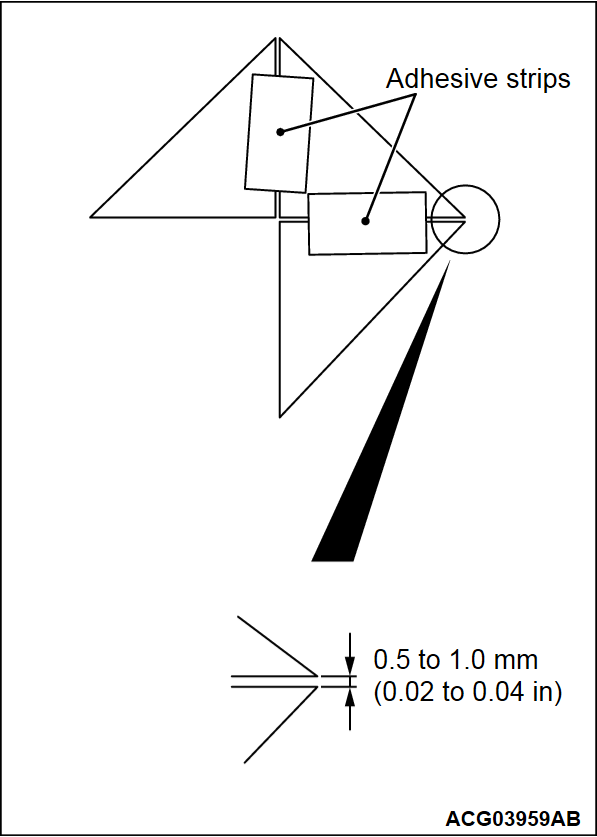
(2) Place the plate pieces and apply adhesive strips together as shown. When the plate pieces are covered with a protective film, apply the strips on the non-covered surface. (Peel off only one side of films when both sides of the plate pieces are protected)
| note | To make a triangular pyramid, clearance between the plates should be 0.5 to 1.0 mm (0.02 to 0.04 inch). |
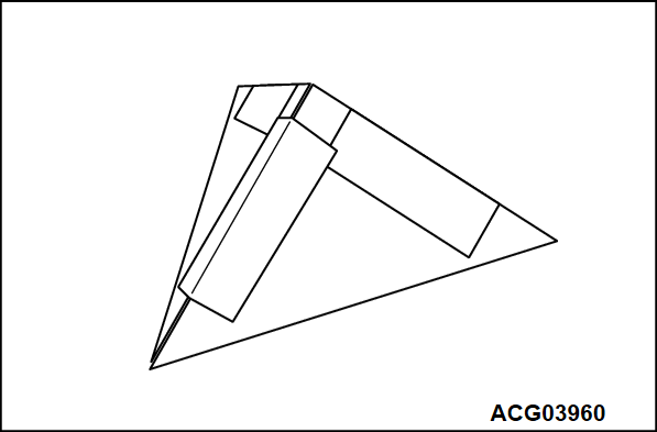
(3) Apply an adhesive strip on the edges to assemble the triangular pyramid as shown.
| note |
|
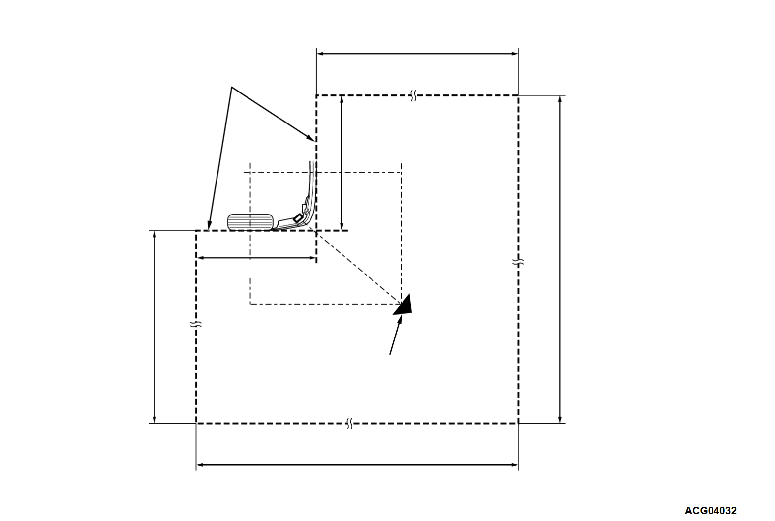
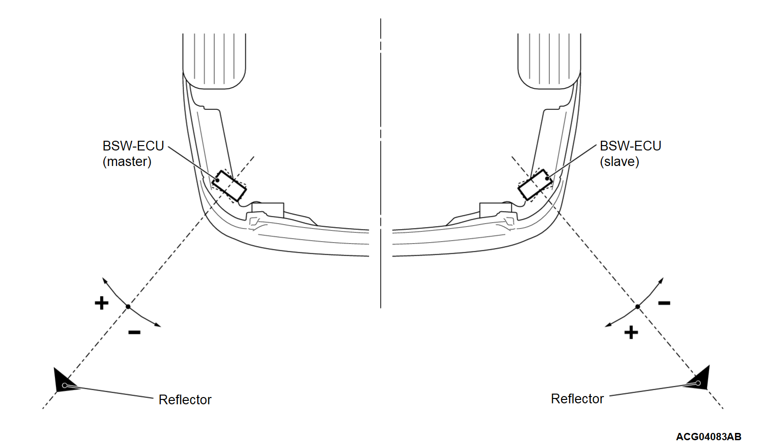
Locating the BSW reflector
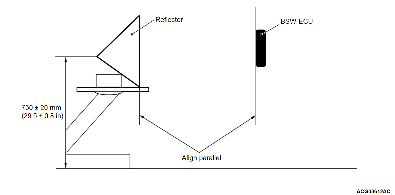
| caution | To carry out an accurate inspection, keep away any metal obstacles other than a bench (e.g. garage jack) where the reflector is placed from the reflector as shown. |
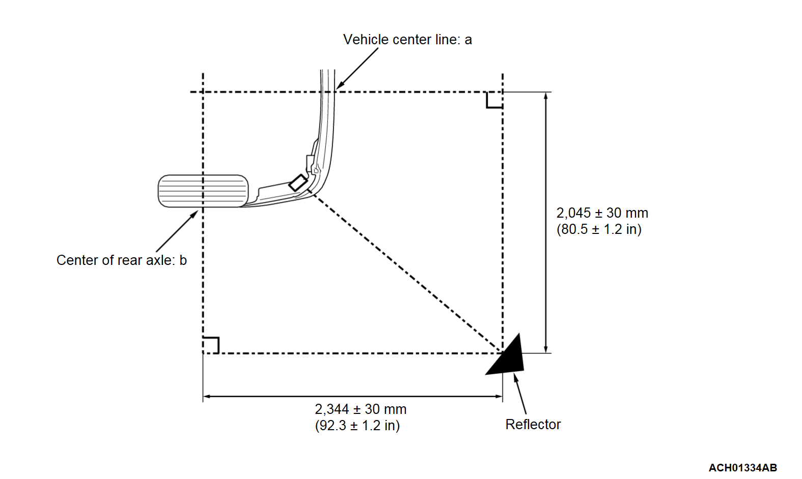
1. Draw line (a) from the center of the Three-diamond mark on the front and rear ends (line a: vehicle center line).
2. Draw line (b) from the center of the Three-diamond mark on the rear wheel (line b: rear axle center line).
3. The bottom of the reflector should be positioned 2,045 ± 30 mm (80.5 ± 1.2 inches) from the vehicle center line and 2,344 ± 30 mm (92.3 ± 1.2 inches) from the rear axle center line.
Check process
Required Special Tools:
- MB992744: Vehicle communication interface-Lite (V.C.I.-Lite)
- MB992745: V.C.I.-Lite main harness A
- MB992747: V.C.I.-Lite USB cable short
- MB992748: V.C.I.-Lite USB cable long
- MB991958: Scan Tool (M.U.T.-III Sub Assembly)
- MB991824: Vehicles Communication Interface (V.C.I.)
- MB991827: M.U.T.-III USB Cable
- MB991910: M.U.T.-III Main Harness A (Vehicles with CAN communication system)
1. Connect the scan tool (M.U.T.-III).
2. Ensure that the BSW system is turned on. If no, operate the blind spot warning switch to turn on the system.
3. Proceed to the steps below on the scan tool (M.U.T.-III):
(1) Select "BSW" or "BSW(SUB)."
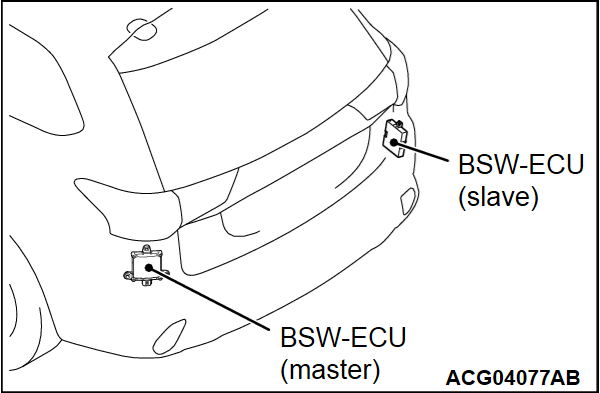
| note | Select "BSW" for the BSW-ECU (master) and "BSW(SUB)" for the BSW-ECU (slave), respectively. |
(2) Select "Special function."
(3) Select "Test."
(4) Select "Radar recognition angle inspection."
![[Previous]](../../../buttons/fprev.png)
![[Next]](../../../buttons/fnext.png)
