[Previous][Next]
REMOVAL AND INSTALLATION
 
 
COLUMN SWITCH ASSEMBLY
caution
  • Before removing the steering wheel and driver’s air bag module assembly, refer to GROUP 52B - Service Precautions and Driver’s Air Bag Module and Clock Spring .
  • After the installation, perform a calibration for the ASC-ECU to learn the steering wheel sensor neutral point. (Refer to GROUP 35C - On-vehicle Service, Steering Wheel Sensor Calibration ).
Pre-removal Operation
  • Steering wheel assembly removal (Refer to GROUP 37 - Steering Wheel ).
  • Steering column lower cover and steering column upper cover removal (Refer to GROUP 37 - Steering Shaft ).
  • Paddle shift assembly removal (Refer to GROUP 37 - Steering Column Shaft Assembly ). <Vehicles with Paddle Shift>
Post-installation Operation
  • Paddle shift assembly installation (Refer to GROUP 37 - Steering column Shaft Assembly ). <Vehicles with Paddle Shift>
  • Steering column lower cover and steering column upper cover installation (Refer to GROUP 37 - Steering Shaft ).
  • Steering wheel assembly installation (Refer to GROUP 37 - Steering Wheel ).
Removal Steps
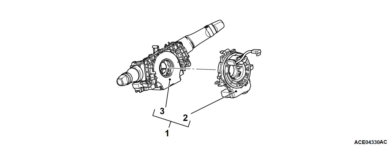
<<A>>>>B<<1.Column switch assembly (Integrated with steering wheel sensor)/Clock spring
>>A<<2.Clock spring
3.Column switch assembly (Integrated with steering wheel sensor)
 
 
REMOVAL SERVICE POINT
 
 
<<A>> COLUMN SWITCH ASSEMBLY/CLOCK SPRING REMOVAL
1.
cautionThe removed clock spring should be stored in a clean, dry place.
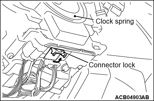
Lift the connector lock of clock spring connector to the direction of the arrow, then unlock and disconnect the connector.
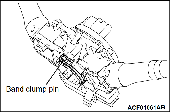
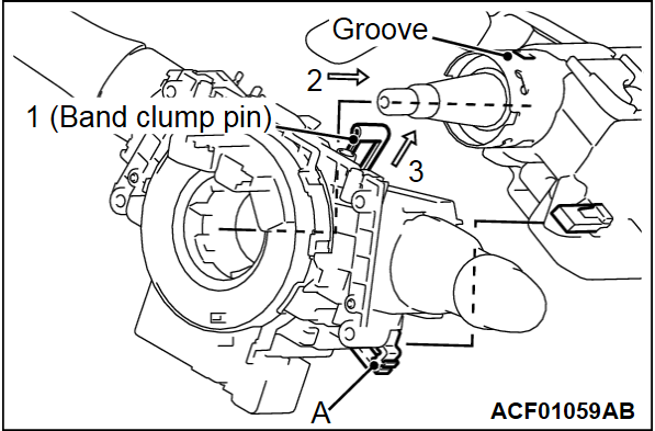
2. Using a pliers or similar tool, pinch and lift the band clump pin shown in the figure.
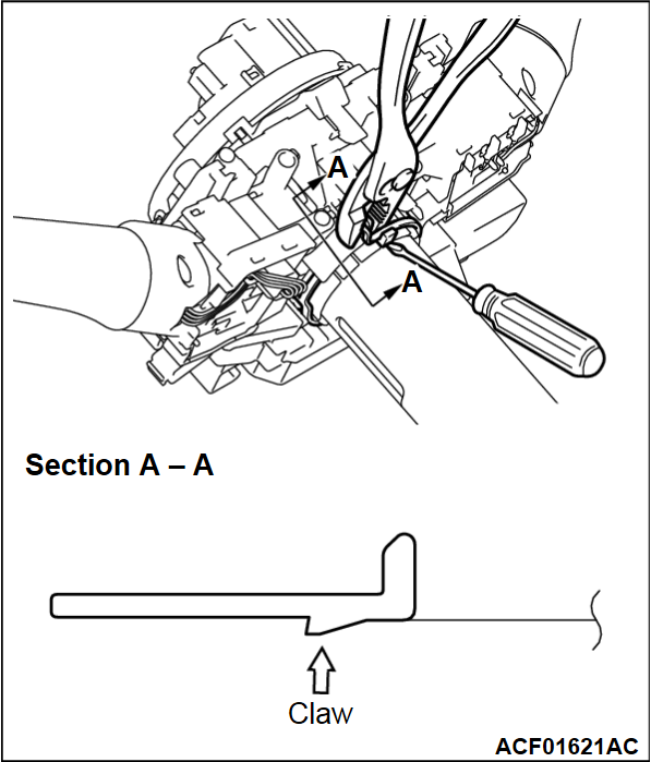
3. With the flat-tipped screwdriver inserted into the column shaft groove shown in the figure, lift the claw shown in Section A - A, and then remove the column switch assembly by pulling out the column switch assembly.


INSTALLATION SERVICE POINT
 
 
>>A<< CLOCK SPRING INSTALLATION
Refer to GROUP 52B - Driver’s Air Bag Module and Clock Spring .


>>B<< COLUMN SWITCH ASSEMBLY/CLOCK SPRING INSTALLATION
1. Using a pliers or similar tool, pinch and lift the band clump pin shown in the figure.
2. Align the part "A" position in the figure with the steering lock side rib, and then insert the column switch assembly into the column shaft.
3. After mounting the column switch assembly by securely fitting the column switch assembly claw with the column shaft groove, release the band clump pin.