OSCILLOSCOPE INSPECTION PROCEDURES
With the connector remain connected, connect the oscilloscope probe to each terminal of TCM.
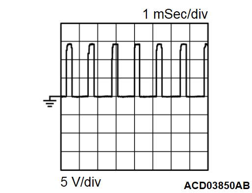
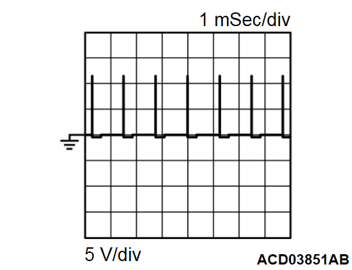
| Terminal No. | Terminal code | Check item | Check conditions | Normal conditions | Wave patterns | |
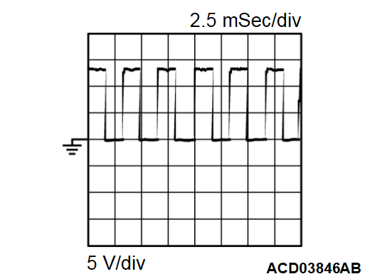
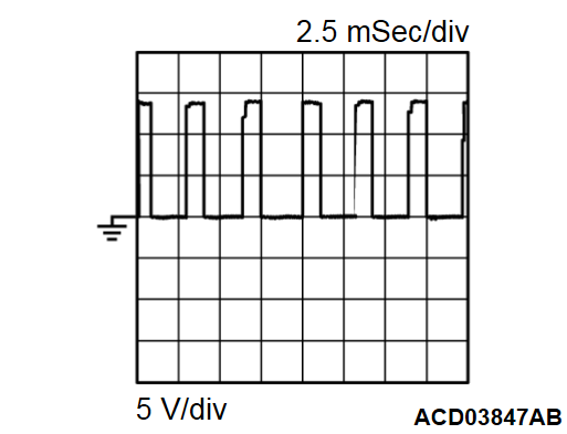
| 1 | PLLS | Line pressure solenoid valve |
| Accelerator pedal: Fully closed | ON pulse (activation signal) width (Long) | Wave pattern A |
| Accelerator pedal: Fully opened | ON pulse (activation signal) width (Short) | Wave pattern B | ||||
| 2 | PRLS | Primary pressure solenoid valve |
| Pulse signal displayed | Wave pattern A | |
| 3 | SCLS | Secondary pressure solenoid valve |
| Pulse signal displayed | Wave pattern A | |
| 32 | TRBS | Turbine speed sensor |
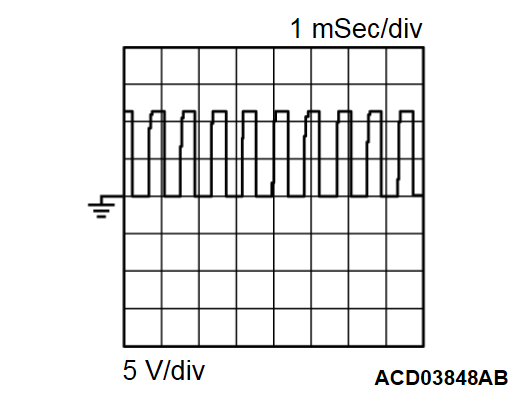
| approx. 1,350 Hz | Wave pattern C | |
| 33 | PRMS | Primary pulley speed sensor |
| approx. 1,350 Hz | Wave pattern C | |
| 34 | SECS | Secondary pulley speed sensor |
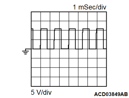
| approx. 165 Hz | Wave pattern D | |
| 41 | LBLS | Select solenoid valve |
| Pulse signal displayed | Wave pattern A | |
| 52 | LULS | Lock-up solenoid valve |
| ON pulse (activation signal) width (Long) | Wave pattern E | |
| ON pulse (activation signal) width (Short) | Wave pattern F | ||||
![[Previous]](../../../buttons/fprev.png)
![[Next]](../../../buttons/fnext.png)
