DTC P0973: Low Clutch Linear Solenoid Valve System (Short circuit)
DTC P0974: Low Clutch Linear Solenoid Valve System (Open circuit)
DTC P0974: Low Clutch Linear Solenoid Valve System (Open circuit)
DESCRIPTIONS OF MONITOR METHODS
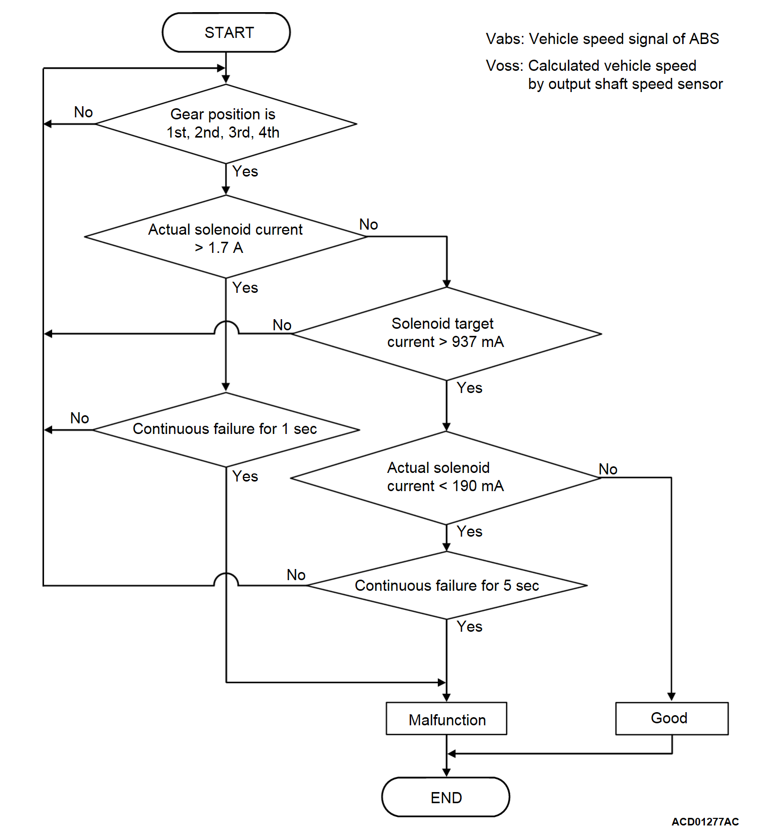
- During 1st gear driving or 4th gear driving, an abnormal value equivalent to short circuit is detected in the solenoid control current for 1 second. <P0973>
- During 1st gear driving or 4th gear driving, an abnormal value equivalent to open circuit is detected in the solenoid control current for 5 seconds. <P0974>
MONITOR EXECUTION
- 1st to 4th gear driving
MONITOR EXECUTION CONDITIONS (OTHER MONITOR AND SENSOR)
Other Monitor (There is no temporary DTC stored in memory for the item monitored below)
- P0731: 1st gear incorrect ratio
- P0732: 2nd gear incorrect ratio
- P0733: 3rd gear incorrect ratio
- P0734: 4th gear incorrect ratio
- P0735: 5th gear incorrect ratio
- P0729: 6th gear incorrect ratio
Sensor (The sensor below is determined to be normal)
- Not applicable
DTC SET CONDITIONS
Check Conditions <P0973>
- Gear position: 1st to 4th.
Judgment Criteria <P0973>
- Low clutch linear solenoid valve actual current: more than 1.7 A (1 second)
Check Conditions <P0974>
- Gear position: 1st to 4th.
- Low clutch linear solenoid valve activation command: more than 937 mA
Judgment Criteria <Circuit continuity open>
- Low clutch linear solenoid valve actual current: less than 190 mA. (5 seconds)
OBD-II DRIVE CYCLE PATTERN
Drive in 1st to 4th gears. Maintain each shift range for approximately 10 seconds.
PROBABLE CAUSES
- Malfunction of the low clutch linear solenoid valve system circuit
- Damaged harness or connector
- Malfunction of the TCM
- Malfunction of the low clutch linear solenoid valve (valve body assembly)
DIAGNOSIS
STEP 1. Check the TCM terminal voltage.
[TCM connector (harness side, connected)]
Measure the voltage between the LOLS terminal and body ground.
- Low clutch engaged: 300 Hz
- Other than above: 0 V
Is the check result normal?
STEP 2. Check for continuity in LOLS line between the TCM connector and A/T control solenoid valve assembly connector.
When the continuity check result is OK, check that the wiring harness is not shorted to the body and other wiring harness. Repair the connector(s) or wiring harness.
Is the check result normal?
 Repair the connector(s) or wiring harness.
STEP 3. Check the low clutch linear solenoid.
STEP 4. Check for continuity in signal line between the A/T control solenoid valve assembly connector and the low clutch linear solenoid valve connector.
Is the check result satisfactory?
 Replace the valve body assembly.
 Repair the connector(s) or wiring harness.
STEP 5. Check the TCM and A/T control solenoid valve assembly connector pin terminals and the connection status.
STEP 6. Check the TCM and A/T control solenoid valve assembly connector pin terminals and the connection status.
Is the check result normal?
 Replace the TCM.
 Repair or replace the failure section.
![[Previous]](../../../buttons/fprev.png)
![[Next]](../../../buttons/fnext.png)

