DTC P0893: Interlock Detection
DESCRIPTIONS OF MONITOR METHODS
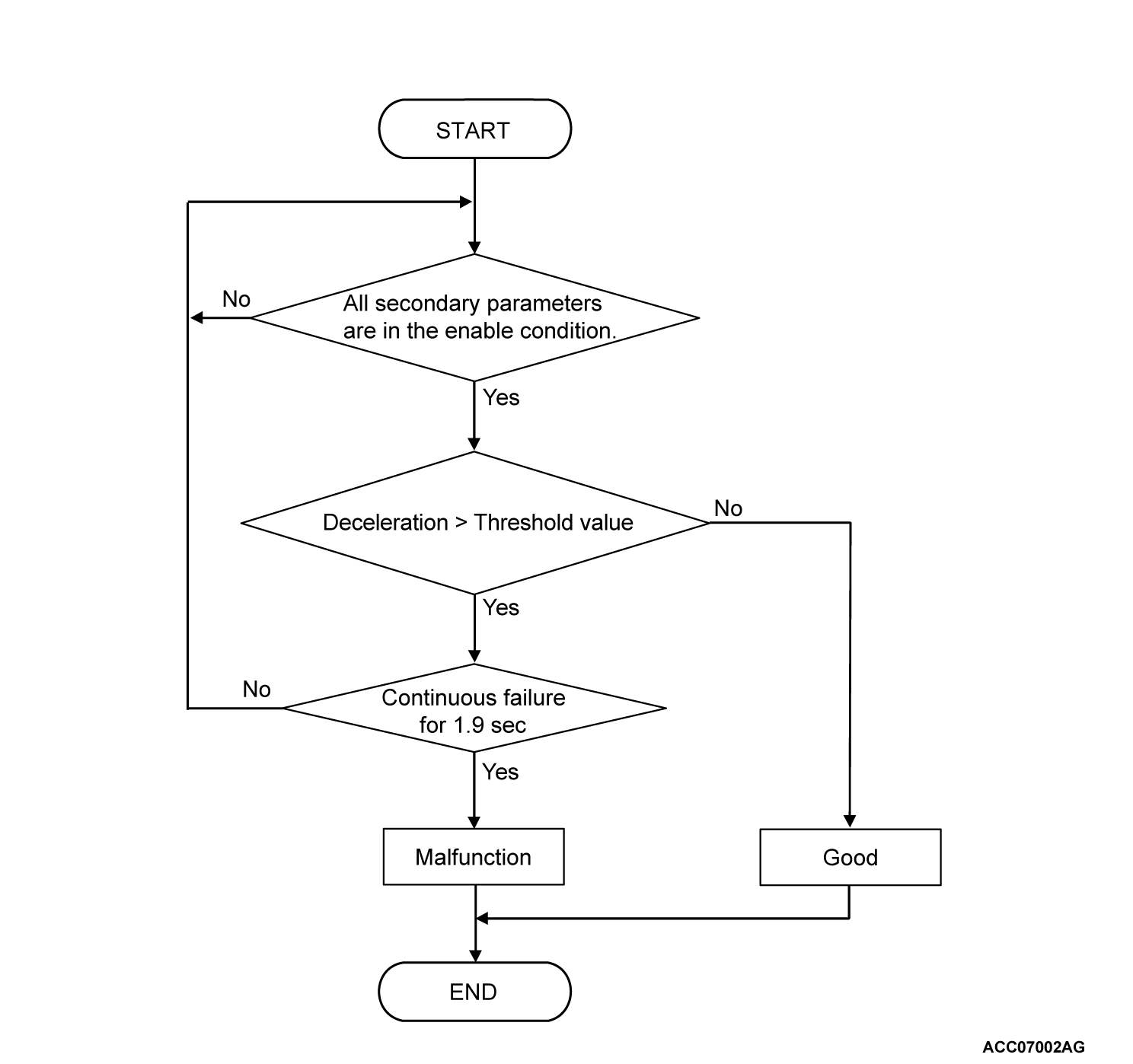
- With the stoplight switch signal and output shaft speed sensor being normal, the fast deceleration exceeding the set time is detected.
- Output failure to the solenoid, open or short circuit
- Hydraulic switch pattern, hydraulic switch open or short circuit
- Open circuit of the output shaft speed sensor or poor connection of the connector
MONITOR EXECUTION
- Continuous
MONITOR EXECUTION CONDITIONS (OTHER MONITOR AND SENSOR)
Other Monitor (There is no temporary DTC stored in memory for the item monitored below)
- Not applicable
Sensor (The sensor below is determined to be normal)
- Not applicable
DTC SET CONDITIONS
Check Conditions
- Fluid pressure switch status combination: not designed combination
- Stoplight switch signal: OFF.
Judgment Criteria
- Deceleration: more than threshold value. (1.9 second)
OBD-II DRIVE CYCLE PATTERN
Start the engine, drive at 60 km/h (37.3 mph) or more for 15 minutes in total.
PROBABLE CAUSES
- When the DTC P0720: Output shaft speed sensor system circuit is stored
- Damaged harness or connector
- When the DTC P0846: 2-6 brake pressure switch system is stored
- When the DTC P0876: High clutch pressure switch system is stored
- When the DTC P0962, P0963: Line pressure linear solenoid valve system is stored
- When the DTC P0973, P0974: Low clutch linear solenoid valve system is stored
- When the DTC P0976, P0977: 2-6 brake linear solenoid valve system is stored
- When the DTC P0979, P0980: 3-5 reverse clutch linear solenoid valve system is stored
- When the DTC P0982, P0983: high clutch linear solenoid valve system is stored
- When the DTC P0988: Low-reverse brake pressure switch is stored
- When the DTC P0998, P0999: low clutch shift solenoid valve system is stored
- When the DTC P099B, P099C: Low-reverse brake shift solenoid valve system is stored
- When the DTC P2763, P2764: Lock-up and Low-reverse brake linear solenoid valve system is stored
DIAGNOSIS
STEP 1. Check the DTC.
Check if the following DTCs are stored. Repair or replace the failure section.
- P0720 Output shaft speed sensor
- P0846 2-6 brake pressure switch
- P0876 High clutch pressure switch
- P0962 Line pressure linear solenoid valve system <Short circuit>
- P0963: Line pressure linear solenoid valve system <Open circuit>
- P0973 Low clutch linear solenoid valve system <Short circuit>
- P0974 Low clutch linear solenoid valve system <Open circuit>
- P0976: 2-6 brake linear solenoid valve system <Short circuit>
- P0977: 2-6 brake linear solenoid valve system <Open circuit>
- P0979 3-5 reverse clutch linear solenoid valve system <Short circuit>
- P0980 3-5 reverse clutch linear solenoid valve system <Open circuit>
- P0982: High clutch linear solenoid valve system <Short circuit>
- P0983: High clutch linear solenoid valve system <Open circuit>
- P0988 Low-reverse brake pressure switch
- P0998: Low clutch shift solenoid valve system <Short circuit>
- P0999: Low clutch shift solenoid valve system <Open circuit>
- P099B Low-reverse brake shift solenoid valve system <Short circuit>
- P099C Low-reverse brake shift solenoid valve system <Open circuit>
- P2763 Lock-up and Low-reverse brake linear solenoid valve system <Short circuit>
- P2764 Lock-up and Low-reverse brake linear solenoid valve system <Open circuit>
Is the check result normal?
 Repair or replace the failure section.
STEP 2. Check TCM related to the solenoid, pressure switch and output shaft speed sensor, the A/T control solenoid valve assembly connector pin terminals, and the connection status.
Is the check result normal?
 Repair or replace the failure section.
STEP 3. Erase the DTC, and drive the vehicle for a while.
Check that the normal code is displayed. The procedure is complete.
 Replace the transaxle assembly.
Is the check result normal?
 The procedure is complete.
 Replace the transaxle assembly.
![[Previous]](../../../buttons/fprev.png)
![[Next]](../../../buttons/fnext.png)

