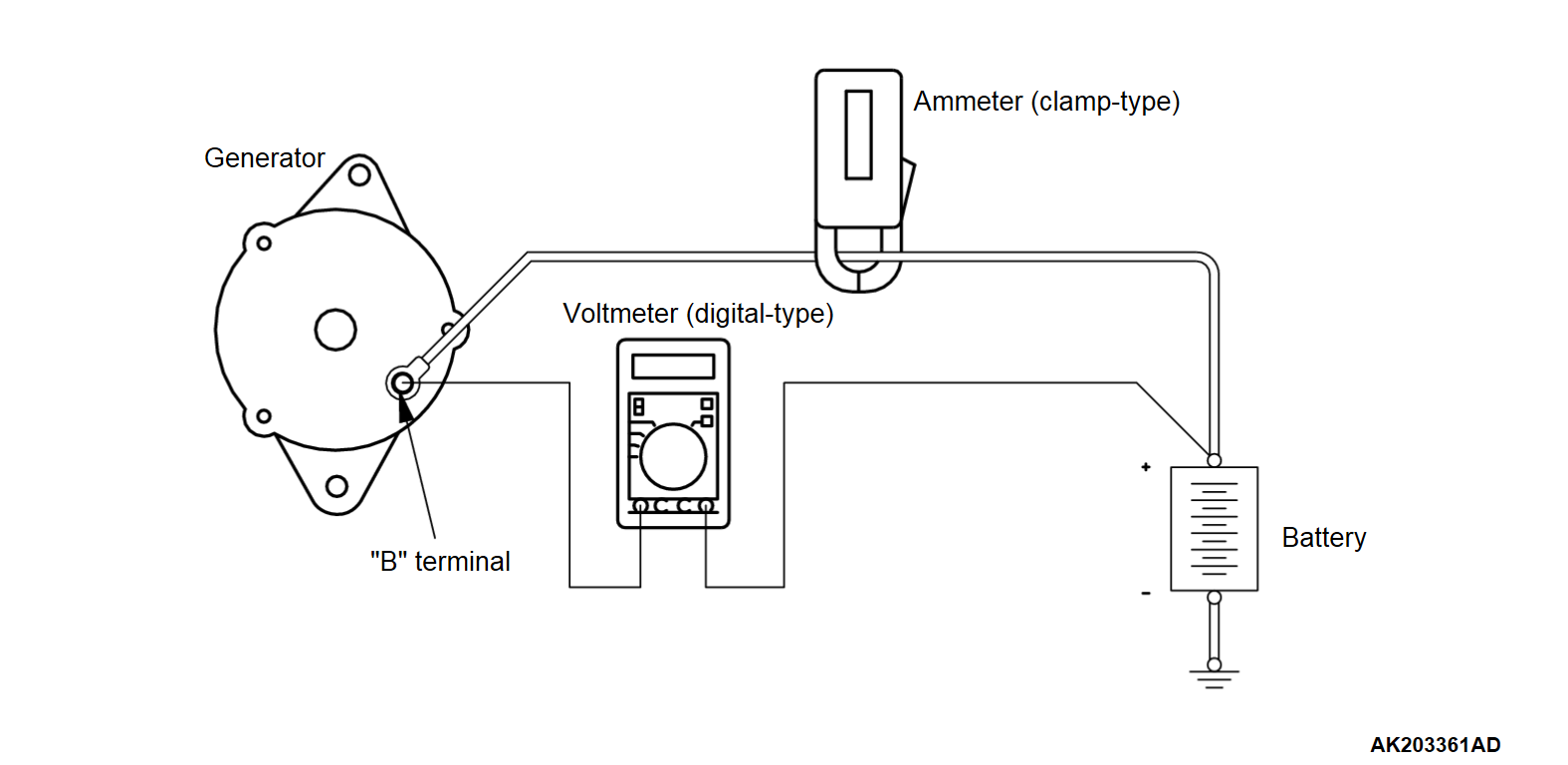
GENERATOR OUTPUT LINE VOLTAGE DROP TEST
Required Special Tools:
- MB992744: Vehicle communication interface-Lite (V.C.I.-Lite)
- MB992745: V.C.I.-Lite main harness A
- MB992747: V.C.I.-Lite USB cable short
- MB992748: V.C.I.-Lite USB cable long
- MB991958: Scan Tool (M.U.T.-III Sub Assembly)
- MB991824: Vehicles Communication Interface (V.C.I.)
- MB991827: M.U.T.-III USB Cable
- MB991910: M.U.T.-III Main Harness A (Vehicles with CAN communication system)
This test determines whether the wiring from the generator "B" terminal to the positive battery terminal (including the fusible line) is in a good condition or not.
1.
| warning | Battery posts, terminals and related accessories contain lead and lead compounds. Wash hands after handling. |
Always be sure to check the following before the test.
2. Turn the ignition switch to the "LOCK" (OFF) position.
3. Disconnect the negative battery cable.
4. Set a clamp-type DC test ammeter to the generator "B" terminal output wire.
| note | Disconnecting the generator output wire and connecting the ammeter may not thoroughly diagnose an generator output line resistance increase problem because of an insufficient connection between terminal "B" and the output wire. |
5. Connect a digital-type voltmeter between the generator "B" terminal and the positive battery terminal. (Connect the positive lead of the voltmeter to the "B" terminal and connect the negative lead of the voltmeter to the positive battery cable).
6. Reconnect the negative battery cable.
7.
| caution | To prevent damage to scan tool (M.U.T.-III), always turn the ignition switch to the "LOCK" (OFF) position before connecting or disconnecting scan tool (M.U.T.-III). |
8. Leave the hood open.
9. Start the engine.
10. With the engine running at 2,500 r/min, turn the headlights and other lights on and off to adjust the generator load so that the value displayed on the ammeter is slightly above 30 A.
Adjust the engine speed by gradually decreasing it until the value displayed on the ammeter is 30 A. Take a reading of the value displayed on the voltmeter at this time.
Limit: Maximum 0.3 V
| note | When the generator output is high and the value displayed on the ammeter does not decrease until 30 A, set the value to 40 A. Read the value displayed on the voltmeter at this time. When the value range is 40 A, the limit is maximum 0.4 V. |
11. If the value displayed on the voltmeter is above the limit value, there is probably a malfunction in the generator output wire, so check the wiring between the generator "B" terminal and the positive battery terminal (including fusible link).
If a terminal is not sufficiently tight or if the harness has become discolored due to overheating, repair and then test again.
12. After the test, run the engine at idle.
13. Turn off all lights.
14. Turn the ignition switch to the "LOCK" (OFF) position.
15. Disconnect the scan tool (M.U.T.-III) to the data link connector.
16. Disconnect the negative battery cable.
17. Disconnect the ammeter and voltmeter.
18. Connect the negative battery cable.
![[Previous]](../../../buttons/fprev.png)
![[Next]](../../../buttons/fnext.png)

