DTC P0421: Warm Up Catalyst Efficiency Below Threshold
TECHNICAL DESCRIPTION
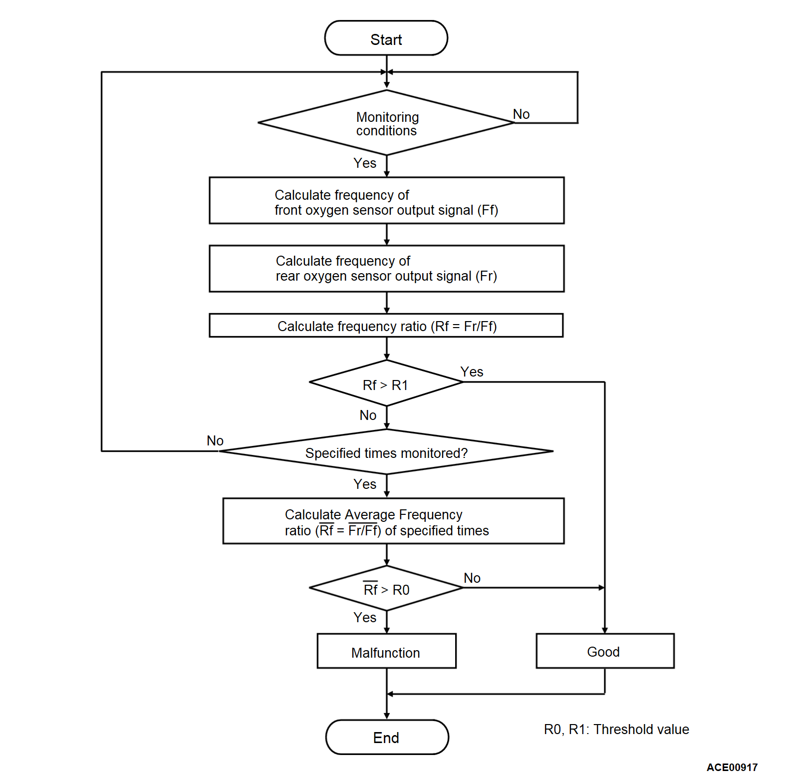
- The signal from the heated oxygen sensor (rear) differs from the linear air-fuel ratio sensor, because the catalytic converter purifies exhaust gas. When the catalytic converter has deteriorated, the signal from the linear air-fuel ratio sensor becomes similar to the heated oxygen sensor (rear).
- The ECM compares the output of the linear air-fuel ratio sensor and heated oxygen sensor (rear) signals.
DESCRIPTIONS OF MONITOR METHODS
- Linear air-fuel ratio sensor and heated oxygen sensor (rear) rich/lean switching frequencies are nearly equal.
MONITOR EXECUTION
- Continuous
MONITOR EXECUTION CONDITIONS (Other monitor and Sensor)
Other Monitor (There is no temporary DTC set in memory for the item monitored below)
- Linear air-fuel ratio sensor monitor
- Heated oxygen sensor (rear) monitor
- Linear air-fuel ratio sensor heater monitor
- Heated oxygen sensor (rear) heater monitor
- Heated oxygen sensor offset voltage monitor
- Misfire monitor
- Fuel system monitor
- Heated oxygen sensor (rear) feedback control system
Sensor (The sensor below is determined to be normal)
- Mass airflow sensor
- Engine coolant temperature sensor
- Intake air temperature sensor
- Barometric pressure sensor
- Throttle position sensor
- Accelerator pedal position sensor
Check Conditions
- Engine speed is lower than 3,000 r/min.
- Accelerator pedal is depressed.
- Mass airflow is between 13 and 45 g/sec.
- More than 3 seconds have elapsed after the above-mentioned three conditions have been met.
- More than 70 seconds have passed since the engine starting sequence was completed.
- Heated oxygen sensor (rear) output voltage with ground offset is more than 0.4 volt.
- Intake air temperature is higher than -10°C (14°F).
- Barometric pressure is higher than 76 kPa (22.4 in.Hg).
- Under the closed loop air/fuel ratio control.
- Vehicle speed is 1.5 km/h (1.0 mph) or more.
- The ECM monitors the maximum 4 times per drive cycle under these conditions.
- Short-term fuel trim is higher than -25 percent and lower than +25 percent.
- The cumulative mass airflow is higher than 800 g.
- The linear air-fuel ratio sensor rich/lean switching frequency is more than 6 times.
Judgment Criterion
- When the monitoring for 10 seconds is carried out 5 times, the frequency ratio of heated oxygen sensor (rear) and linear air-fuel ratio sensor signals is the specified value or more.
note The specified value varies depending on the average air flow rate.
FAIL-SAFE AND BACKUP FUNCTION
- None
TROUBLESHOOTING HINTS (The most likely causes for this code to be set are:)
- Catalytic converter deteriorated.
- ECM failed.
DIAGNOSIS
Required Special Tools:
- MB992744: Vehicle communication interface-Lite (V.C.I.-Lite)
- MB992745: V.C.I.-Lite main harness A
- MB992747: V.C.I.-Lite USB cable short
- MB992748: V.C.I.-Lite USB cable long
- MB991958: Scan Tool (M.U.T.-III Sub Assembly)
- MB991824: Vehicles Communication Interface (V.C.I.)
- MB991827: M.U.T.-III USB Cable
- MB991910: M.U.T.-III Main Harness A (Vehicles with CAN communication system)
![[Previous]](../../../buttons/fprev.png)
![[Next]](../../../buttons/fnext.png)


