BATTERY CURRENT SENSOR CALIBRATION <2.4L ENGINE>
PURPOSE
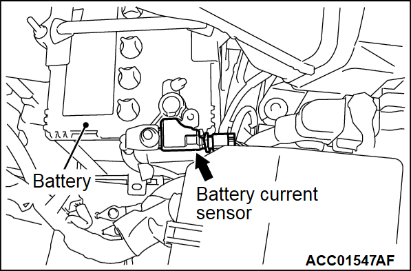
The ECM carries out the electrical generation control according to the charge level of the battery, based on the battery current sensor signal. To improve the effect of reducing the fuel consumption by the electrical generation control, it is necessary to accurately detect the charge level of the battery. For this, if the following services are performed, carry out the battery current sensor calibration.
- Replacing the battery current sensor
- Replacing the ECM
LEARNING PROCEDURE
Required Special Tools:
- MB992744: Vehicle communication interface-Lite (V.C.I.-Lite)
- MB992745: V.C.I.-Lite main harness A
- MB992747: V.C.I.-Lite USB cable short
- MB992748: V.C.I.-Lite USB cable long
- MB991958: Scan Tool (M.U.T.-III Sub Assembly)
- MB991824: Vehicles Communication Interface (V.C.I.)
- MB991827: M.U.T.-III USB Cable
- MB991910: M.U.T.-III Main Harness A (Vehicles with CAN communication system)
| caution | Before connecting or disconnecting the scan tool (M.U.T.-III), turn the ignition switch to the "LOCK" (OFF) position. |
1. After the ignition switch is in "LOCK" (OFF) position, disconnect the battery cable from the negative battery terminal.
2. Remove the battery current sensor from the battery cable (Do not disconnect the battery current sensor connector).
3. Connect the battery cable without the battery current sensor to the negative battery terminal.
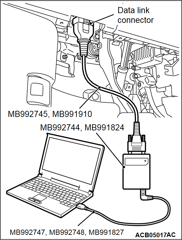
4. Connect the scan tool (M.U.T.-III) to the data link connector as follows.
| note | For details on how to use the scan tool (M.U.T.-III), refer to the "M.U.T.-III Owner's Manual." |
5. Start up the personal computer.
6. Connect special tool MB992747/MB992748 or special tool MB991827 to special tool MB992744 or special tool MB991824 and the personal computer.
7. Connect special tool MB992745 or special tool MB991910 to special tool MB992744 or special tool MB991824.
8. Connect special tool MB992745 or special tool MB991910 to the data link connector.
| note | When the special tool MB992745 is connected to the data link connector, the special tool MB992744 indicator light will be illuminated in a green color. |
9. Turn the power switch of special tool MB991824 to the "ON" position. <When using the special tool MB991824>
| note | When special tool MB991824 is energized, special tool MB991824 indicator light will be illuminated in a green color. |
10. Start the scan tool (M.U.T.-III) system on the personal computer and turn the ignition switch to the "ON" position.
11. Select "MFI" from System select Screen of the scan tool (M.U.T.-III).
12. Select "Special Function" from MFI Screen.
13. Select "Learning" from Special Function Screen.
14. Select "Battery current SNSR.calibration" from Learning Screen.
15. Start the calibration by pressing the "OK" button.
16. Confirm that the scan tool (M.U.T.-III) data list item No. 119 Battery current sensor calibration is "Completed".
17. After the ignition switch is in "LOCK" (OFF) position, disconnect the scan tool (M.U.T.-III).
18. Install the battery current sensor.
![[Previous]](../../../buttons/fprev.png)
![[Next]](../../../buttons/fnext.png)

